Method And Device For Assessing Residual Service Life Of Rolling Bearing

a technology of residual service life and rolling bearing, which is applied in the direction of fluid pressure measurement by mechanical elements, solid vibration measurement, machine part testing, etc., can solve the problems of increased vibration, unbalance or misalignment of rolling bearings, and affect the service life of these rolling bearings, and achieves the effect of higher precision

Inactive Publication Date: 2007-12-06
THE CHUGOKU ELECTRIC POWER CO INC +1
View PDF14 Cites 86 Cited by
  • Summary
  • Abstract
  • Description
  • Claims
  • Application Information

AI Technical Summary

Benefits of technology

[0055] In the assessment method configured as described above, baseline data acquired by the testing device concerning the relationship of bearing acceleration to wear particle intrusion and the relationship of the acceleration to the lubricant state are acquired in advance in the baseline data acquisition means for the state of formation of indentations in the rolling bearings that occur when the lubrication degrades due to contamination with wear particles or degradation of the lubricant. In the measurement means, vibration signals are obtained, and resonance frequency band signals or high-frequency signals detectable at the highest sensitivity are measured using the accelerometer (4) for a diagnostic rolling bearing (3) residing on a rotating device (1, 2) for the purpose of assessing the remaining service life.
[0056] The states of wear particle contamination and lubricant degradation of the diagnostic rolling bearing (3) are then estimated, and the remaining service life of the diagnostic rolling bearing (3) is computed in the determination means using the measured values obtained by the measurement means, the data obtained by the baseline data acquisition means, and vibration data relating to the bearing load in the normal state of the diagnostic rolling bearing (3) measured in advance, to the rotational speed, the operation time, and to the rolling bearing designation.
[0057] In this determination means, it is first determined, by computing the increase in vibration, whether the diagnostic rolling bearing (3) is in an early stage or a late stage of degradation.
[0058] When a determination is made that the bearings are in an early stage of degradation, further determination is performed as follows. First, a determination is made as to whether the diagnostic rolling bearing (3) has a normal degree of degradation, is contaminated with wear particles to a certain degree, or has undergone lubricant degradation to a certain degree. The determination is made using the resonance frequency band signals or high-frequency band signals of the accelerometer (4) for the diagnostic rolling bearing (3) obtained in the measurement means, and the pre-measured vibration data during normal operation of the diagnostic rolling bearing (3).
[0059] The rated service life is computed as the remaining service life when a determination is made that the diagnostic rolling bearing (3) is not contaminated with wear particles, there is no lubricant degradation, and the bearings are in a normal state albeit in an initial stage of degradation. Then, when a determination is made that the diagnostic rolling bearing (3) is contaminated with wear particles and is in an initial stage of degradation, the size of the penetrated wear particles is estimated from the vibration data in the baseline data acquisition means, and the remaining service life is computed. Furthermore, when the lubricant of the diagnostic rolling bearing (3) has deteriorated, the bearings are determined to be in an initial stage of degradation, the degradation of the lubricant is estimated from the vibration data in the data acquisition means, and the remaining service life is computed.
[0060] Lastly, when a late stage of degradation is determined, the remaining service life is computed based on the increase of the low-frequency band vibration of the acceleration. At this time, the remaining service life can be computed with higher precision in the assessment method of the present invention not only by predicting increases in vibration, but also by observing the time elapsed until a sharp increase in acceleration occurs after wear particle contamination or lubricant degradation.

Problems solved by technology

Therefore, the service life of these rolling bearings is affected by two types of failures that include “spalling due to concentrated stress” in portions where there is a buildup of asperities due to contamination with impurities, and “increased vibration” due to an increase in the roughness of the surface of the orbit of the rolling bearing when the lubricating film of grease is broken by moisture contamination.
Causes for defects include unbalance or misalignment of rolling bearings, looseness in the substructure, and other factors.

Method used


Image

  • Method And Device For Assessing Residual Service Life Of Rolling Bearing
  • Method And Device For Assessing Residual Service Life Of Rolling Bearing
  • Method And Device For Assessing Residual Service Life Of Rolling Bearing

Examples


first embodiment

[0093] Preferred embodiments of the present invention will be described hereinafter with reference to the drawings.

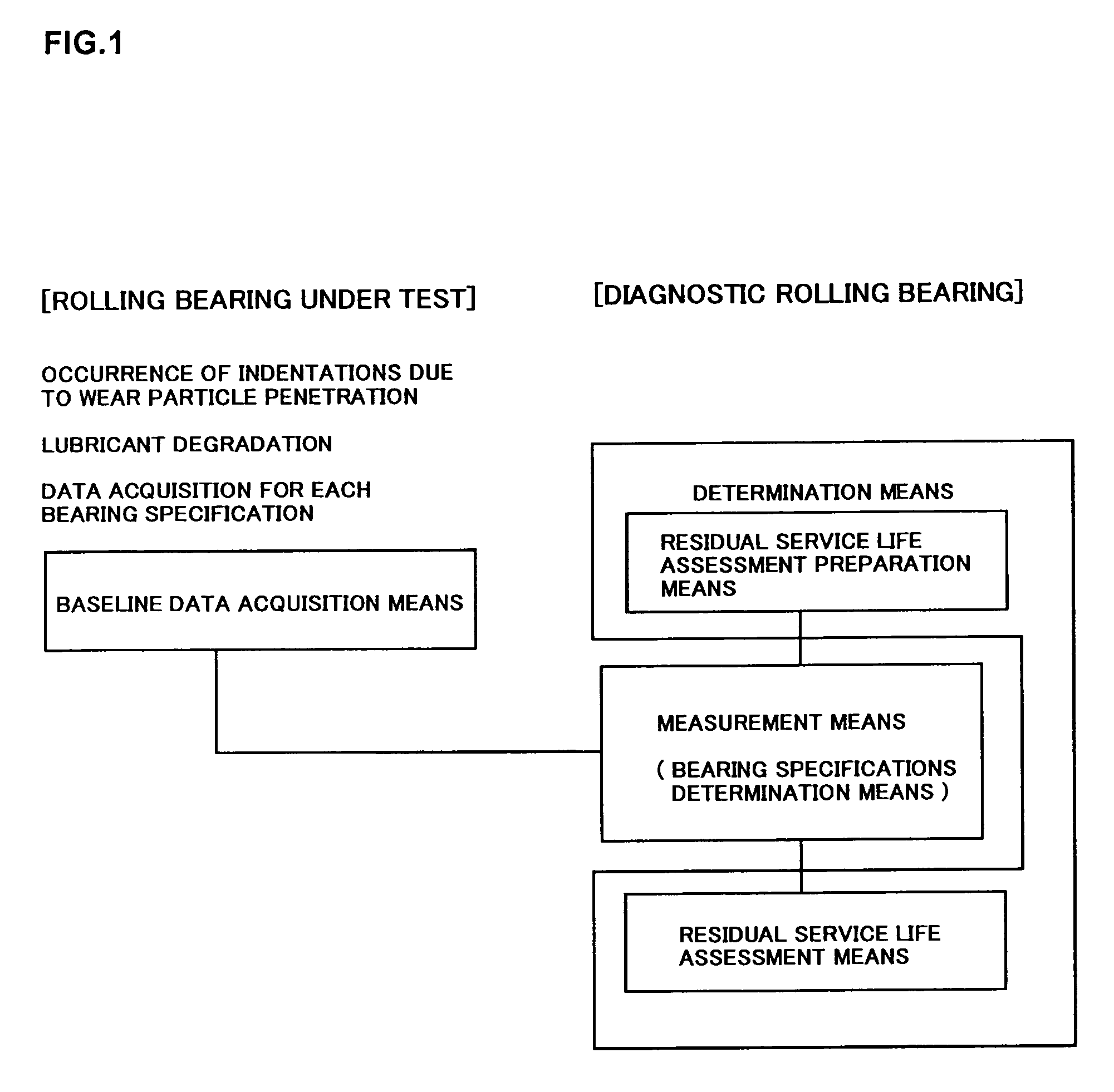
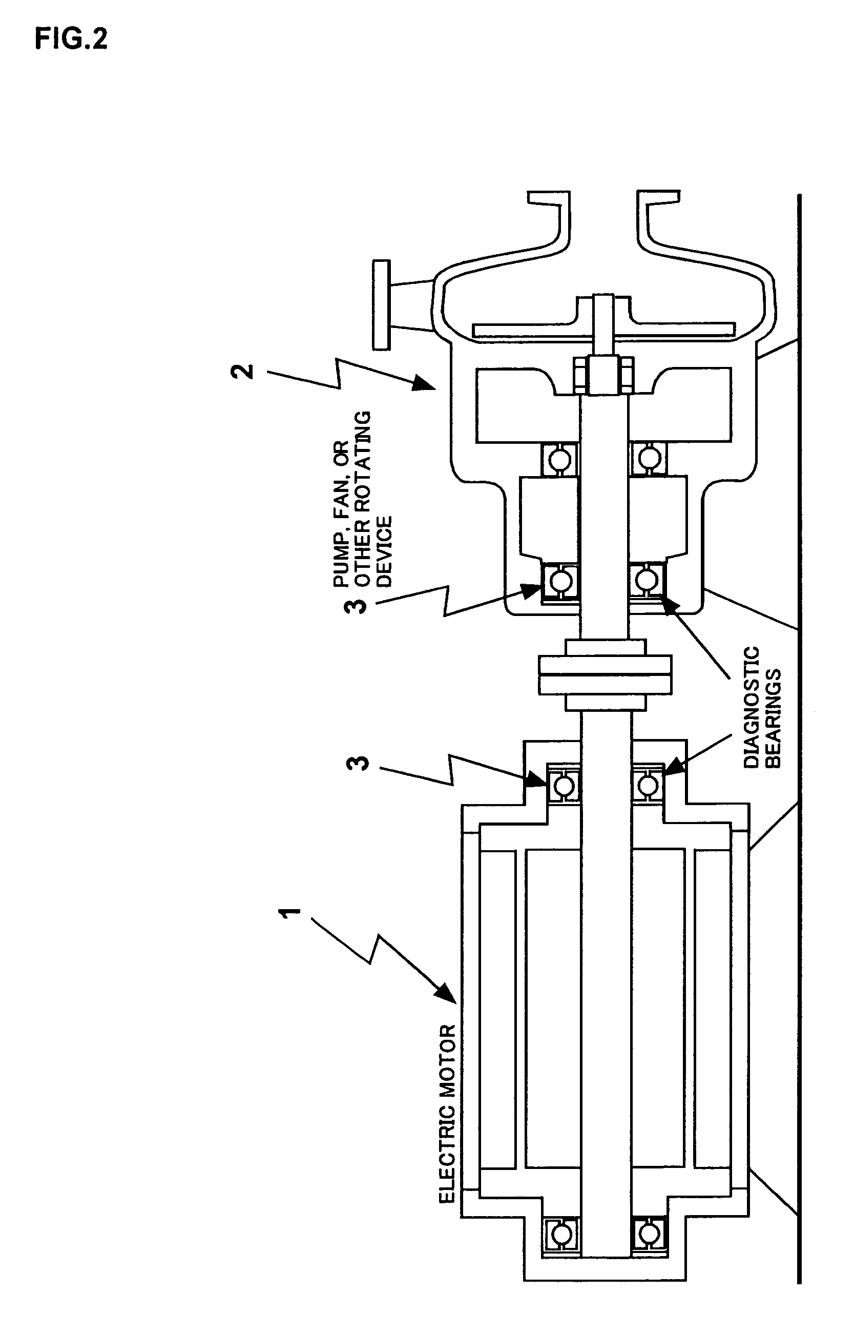
[0094]FIG. 1 is a block diagram illustrating the method for assessing the remaining service life of a rolling bearing according to the present invention. FIG. 2 is a sectional view of an example of rolling bearings residing on an electric motor and a rotating device as the objects for assessment according to the method for assessing remaining service life.

[0095] To obtain baseline data in the baseline data acquisition means, scratches are made directly on the rolling contact surfaces of disassembled bearings to simulate wear particle penetration, resulting in the appearance of indentations on the bearings. To simulate lubricant degradation, bearings having reduced lubricant volumes are then used in tests with a load testing device. An alternative method for simulating wear particle penetration is to introduce a foreign substance into the lubricant in place of wear par...

second embodiment

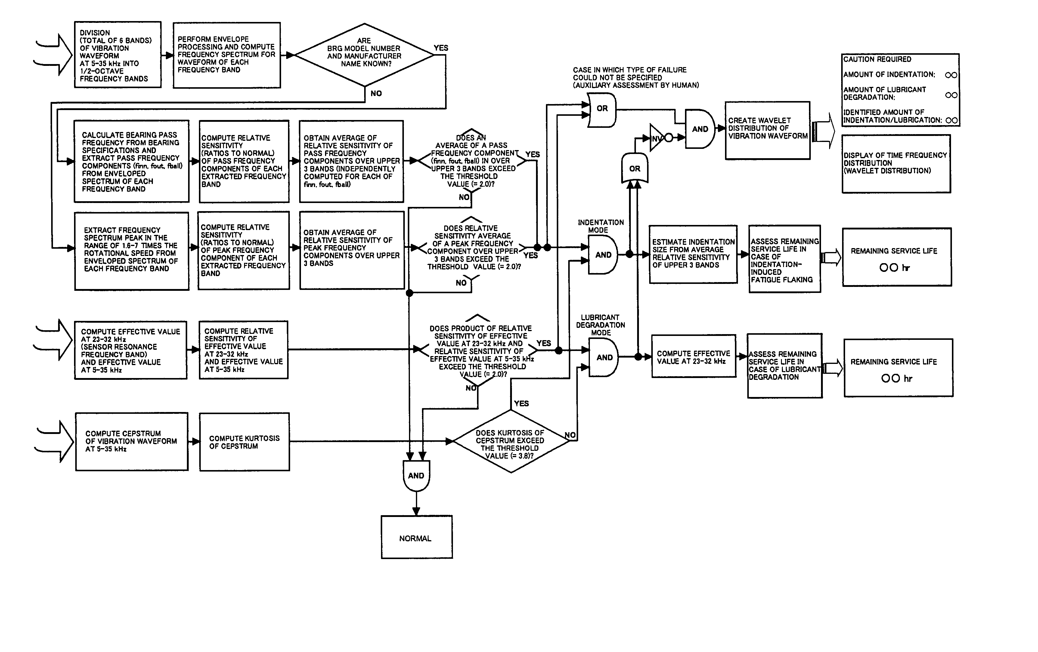
[0113]FIG. 4 is a flowchart illustrating the method for assessing the remaining service life of a rolling bearing in which the model number and name of the manufacturer of the rolling bearing of a second embodiment are determined. FIG. 5 is a flowchart illustrating the method for assessing the remaining service life of a rolling bearing according to a quantitative feature of indentation when the bearing specifications are determined. FIG. 6 is a flowchart illustrating the method for assessing the remaining service life of a rolling bearing according to a quantitative feature of indentation when the bearing specifications are not determined.

[0114] A description is provided of a method for detecting indentation that determines specifications such as the model number and the name of the manufacturer of the rolling bearing (3) of the second embodiment.

[0115] The model number and the name of the manufacturer of the diagnostic rolling bearing (3) are determined by dividing the vibration...

third embodiment

[0154]FIG. 11 is a block diagram of the structure of the device for assessing the remaining service life of a rolling bearing according to the present invention.

[0155] The device for assessing the remaining service life of a rolling bearing has an accelerometer (4), an analog / digital converter (5), a quantitative feature extraction unit (6), a measurement results database (7), a residual service life assessment unit (8), and an assessment results display (9), as well as an output unit for inspection schedules and diagnostic reports (10), and a transmission modem (11).

[0156] The analog / digital converter (5) converts data obtained by the accelerometer (4) on, e.g., a diagnostic rolling bearing (3) whose remaining service life is to be assessed as described above. The quantitative feature extraction unit (6) detects from among the vibration signals converted by the analog / digital converter (5) those signals in the resonance frequency band that are detectable at the highest sensitivit...


PUM


Abstract

Degradation of the lubricant due to contamination of the lubricant with wear particles or moisture, which greatly affects the service life of rolling bearings, can be detected in a cost-effective manner through the use of a resonance frequency band signal or high-frequency signal of an accelerometer, and the service life of a rolling bearing can be estimated with high precision at an early stage on the basis of the detected state of the wear particles and lubricant.
Provided is a method comprising baseline data acquisition means for obtaining vibration signals by using an accelerometer 4 and using a testing device to acquire resonance frequency band signals detectable at the highest sensitivity, for each specification such as model number, manufacturer name, and other specifications for a rolling bearing 3 as pertains to the relationship between the state of wear particle penetration in a rolling bearing 3 and the vibration/bearing service life, and to lubricant degradation and vibration/bearing service life; measurement means whereby an accelerometer 4 is used to obtain vibration signals for the rolling bearing 3 whose remaining service life is being assessed and which resides on a fan, a pump, or another rotating device 1, 2, for the purpose of measuring resonance frequency band signals detectable at the highest sensitivity; and determination means for estimating the state of wear particle penetration and the state of lubricant degradation of the diagnostic rolling bearing 3, and computing the remaining service life of the diagnostic rolling bearing 3 by using measurement values obtained by the measurement means, determination results of the bearing specification determination means, and data obtained by the baseline data acquisition means.

Description

TECHNICAL FIELD [0001] The present invention relates to a method for assessing residual service life of a rolling bearing and to a residual service life assessment device for estimating the remaining service life of a rolling bearing of a pump or fan or a rolling bearing used in a motor for driving these devices as auxiliary machines used in a chemical plant, a steel plant, a power plant, or other facility. BACKGROUND ART [0002] In rolling bearings of pumps and fans that are auxiliary devices used in chemical plants, steel plants, power plants, and other facilities, or in the rolling bearings used in motors for driving these devices, the loads are extremely small, being 5% or less of the rated load, and metal fatigue does not occur therein under normal service conditions. Therefore, the service life of these rolling bearings is affected by two types of failures that include “spalling due to concentrated stress” in portions where there is a buildup of asperities due to contamination ...

Claims


Application Information

Patent Timeline
Patent Type & Authority Applications(United States)
IPC IPC(8): G01M13/04G01H17/00G01M99/00
CPCG01M13/045F16C19/527G01M13/04G01M99/00
Inventor IWATSUBO, TAKUZOSHIROMARU, ISAOTANAKA, MAKOTOAKAMATSU, YOSHINOBUNAGAYASU, YOJINAGAYASU, HIDEKOBODA, SHINGO
Owner THE CHUGOKU ELECTRIC POWER CO INC
Why Eureka
Try Eureka