Multimode MOPA with thermal lens compensation

Inactive Publication Date: 2007-12-06
COHERENT INC
View PDF2 Cites 16 Cited by
  • Summary
  • Abstract
  • Description
  • Claims
  • Application Information

AI Technical Summary

Benefits of technology

[0011]In one aspect, laser apparatus in accordance with the present invention comprises a laser resonator terminated by first and second mirrors. The second mirror serves as an outcoupling mirror of the resonator and defines an outcoupling plane of the laser resonator. An optically-pumped gain-medium is located in the laser resonator. The resonator gain-medium has a thermal lens effect, the magnitude of which is dependent on the power of the optical pumping. The laser resonator is arranged to deliver a beam of laser radiation from the second mirror thereof when said resonator gain-medium is optically p

Problems solved by technology

Within such a flash, thermal loading to the laser rod is not fast enough to spread out and establish an equilibrium thermal lens profile.
In addition, as the pump power or repetition rate is adjusted during operation, the change in the focal length of the thermal lens can easily be on the order of tens of centimeters, thus creating a large change to the propagation parameters of the oscillator beam.
In this case, the above-mentioned mode matching optics will no longer work.
In a prior art MOPA system, wherein the output of the oscillator is sent to the amplifier by mode matching delivery optics, the change of propagation parameters due the changing thermal lens necessarily degrades the amplifier efficiency if the mode matching optics as either designed and optimized without the consideration of the thermal lens or optimized at only one value of pump power or repetition rate.
As noted above, a prior art system that uses a relay lens pair to image the oscillator rod(s) to the amplifier rod(s), will not work well in the presence of thermal lens.
Although this method can address the problem of pump power / thermal lens changes, the requirement of using a same rod diameter in the amplifier necessarily limits critical design criteria of the amplifier such as input beam power density and amplifier gain, compromising the MOPA efficiency.

Method used


Image

  • Multimode MOPA with thermal lens compensation
  • Multimode MOPA with thermal lens compensation
  • Multimode MOPA with thermal lens compensation

Examples


Embodiment Construction

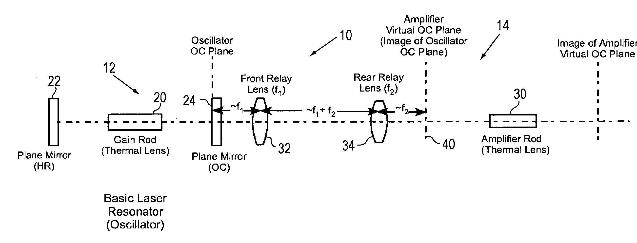
[0027]FIG. 1 illustrates a MOPA 10 formed in accordance with the subject invention. MOPA 10 includes an oscillator 12. Oscillator 12 consists of a laser gain module (rod) 20 positioned between a high reflector 22 and an output coupler 24 from which the laser beam is emitted. In this embodiment, both reflector 22 and output coupler 24 are flat and preferably placed an equal distance away from the ends of the rod 20.

[0028]The laser rod 22, could for example, be formed from Nd:YAG. The rod can be side pumped by several diode bars (not shown). As is well known in the art, a water manifold can be provided for cooling the laser rod and diode bars to stabilize operation. The term “rod” is used in the subject specification and claims to define an elongated solid gain element. Laser rods are often cylindrical with a circular cross section but can also have other shapes such an elliptical or a rectangular with either a rectangular or square cross section.

Thermal Lensing

[0029]It is known that ...


PUM


Abstract

A master oscillator power amplifier (MOPA) laser system includes a symmetrical master oscillator and an amplifier each having an optically pumped solid-state gain rod. An optical relay is located between the laser resonator and the amplifier gain rod. When the oscillator and amplifier gain media are equally optically pumped, the magnification and the distances from the optical relay to the resonator and the amplifier gain rod can be selected such that amplifier efficiency is maximized, independent of optical pump power, even if the diameters of the oscillator and amplifier gain rods are different.

Description

PRIORITY[0001]This application claims priority U.S. Provisional Application, Ser. No. 60 / 811,374, filed Jun. 6, 2006, the disclosure of which is incorporated herein by reference.TECHNICAL FIELD OF THE INVENTION[0002]The present invention relates in general to laser systems including a master oscillator and a power amplifier (MOPA). The invention relates in particular to optical arrangements for coupling a beam from a master oscillator into a power amplifier.DISCUSSION OF BACKGROUND ART[0003]A master oscillator followed by one or more power amplifiers, the so-called MOPA structure, is frequently used in lasers that generate output powers with hundreds or thousands of watts. The output could be in the form of continuous amplitude without modulation in time, the so-called CW output, or of regulated Q-switched pulses.[0004]In a MOPA laser, the master oscillator is used to generate an output that meets all requirements of the desired application. These requirements typically include low ...

Claims


Application Information

Patent Timeline
IPC IPC(8): H01S3/09H01S3/091H01S3/093H01S3/08H01S3/092
CPCH01S3/005H01S3/08072H01S3/094057H01S3/2333H01S3/1611H01S3/1643H01S3/2316H01S3/0941
Inventor WANG, GARY Y.
Owner COHERENT INC
Why Eureka
Try Eureka