Multifunctional Electrophoresis Cassette

Inactive Publication Date: 2007-12-13
SAGE SCI
View PDF0 Cites 86 Cited by
  • Summary
  • Abstract
  • Description
  • Claims
  • Application Information

AI Technical Summary

Benefits of technology

[0026] In another embodiment, there is a device for performing parallel electrophoresis. The device includes a support member adapted a hold a cassette having a plurality of parallel spaced apart el

Problems solved by technology

Loading these wells is typically a time c

Method used


Image

  • Multifunctional Electrophoresis Cassette
  • Multifunctional Electrophoresis Cassette
  • Multifunctional Electrophoresis Cassette

Examples


example 1

Electrophoresis and Electroblotting to Polyvinyl Acetate (PVAc)

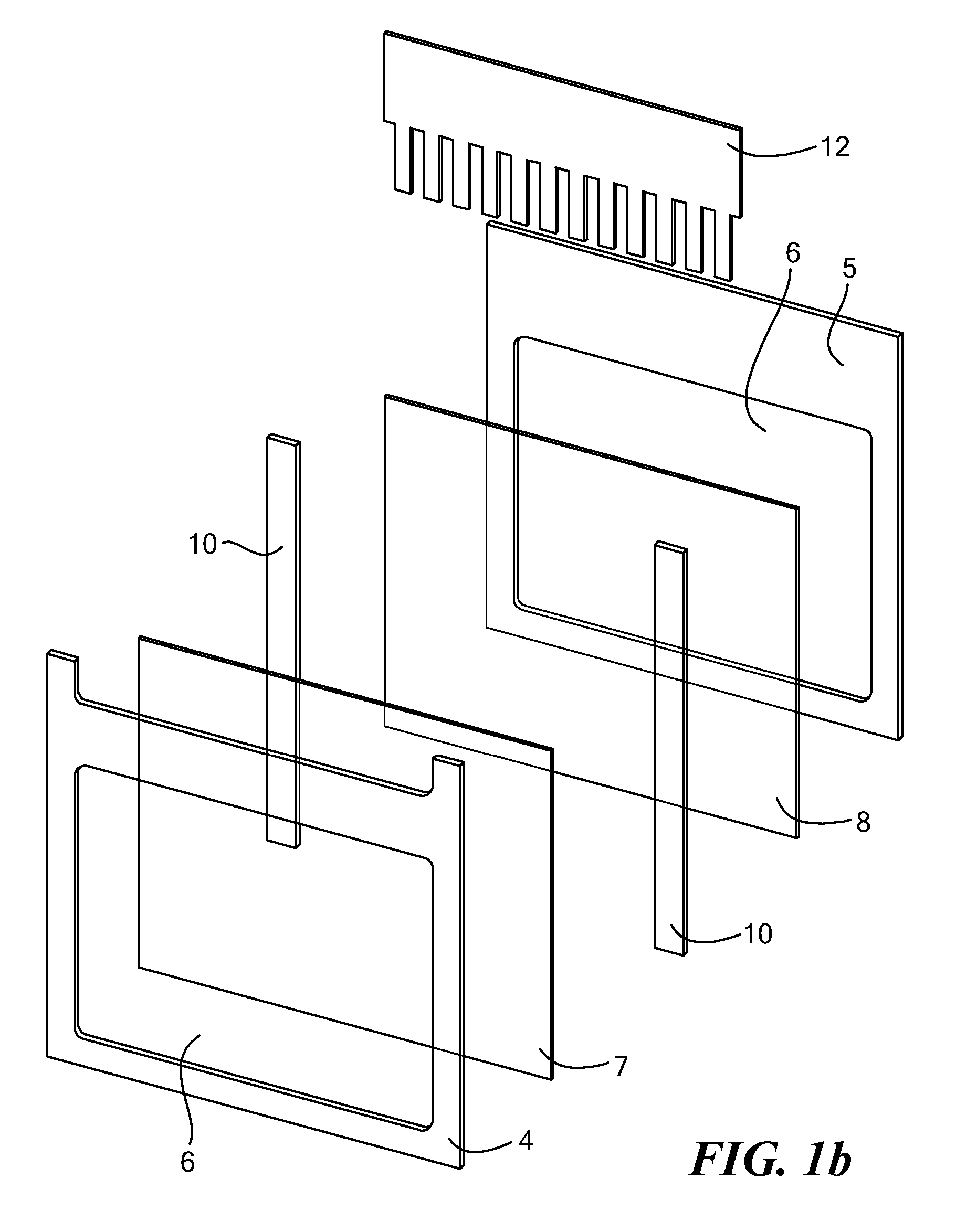
[0086] To determine if protein transferred to membranes integrated during the gel casting process would be adversely affected by a PVAc coating, pre-stained protein standards and liver cell lysate were electrophoresed through a gel 20, and electrotransferred (electroblotted) onto the membrane 8 that had been pre-coated with PVAc prior to gel casting. The membrane was removed and probed with anti-HSP70 antibody for the detection of heat shock protein 70. The results demonstrated that PVAc coating did not adversely affect the immunoblotting process and the gel was recovered for further analysis of the transfer efficiency.

example 2

[0087] Software and a controller are used to control the addition of the insulating fluids to the gel-membrane sandwich assembly 3000, which has an inlet and an outlet and thus acts as a flow cell. When the flow cell chamber(s) 3000 is full, the electrophoresis electrodes become engaged and electrophoresis takes place at the set voltage or current. Fluid is continuously circulated though the flow cell 3000 and cooled by a thermoelectric cooler. A digital display shows that the instrument is in the electrophoresis mode; and the time left until the electrotransfer is completed. At the conclusion of the electrophoresis step, the software switches off the electrophoresis electrodes; activates the transfer pump; removes the insulating fluid to its reservoir; switches valving to the conductive buffer reservoir position and begins to pump the conductive buffer to the flow cell chamber 3000. Once the flow cell chamber 3000 is filled, the software engages the electrotransfer electrodes to be...

example 3

Chemical Welding and Tensioning of Protein Blotting Membrane to Cassette Frames

[0088] Hydrophobic PVDF blotting membrane (Immobilon-FL, Millipore Corp., Bedford, Mass.) was cut to dimensions slighty larger than the windows of PETG front and rear frames (frames 4 and 5 from FIG. 1b). The cut membranes were wet and swollen by brief immersion in MEK (methyl ethyl ketone). The swollen membranes were spread onto a flat glass surface, and contacted with the frames with brief hand pressure. The frames were positioned so that the membrane completely overlapped the inside edges of the window. The frames, with attached PVDF membrane, were removed from the flat surface and the MEK was allowed to evaporate at room temperature. As the MEK evaporated, the membrane the shrank to provide a tight flat surface across the windows of the frames.


PUM

PropertyMeasurementUnit
Electrical conductoraaaaaaaaaa
Distanceaaaaaaaaaa
Electrophoreticaaaaaaaaaa

Abstract

Devices and methods are provided for more efficiently performing electrophoresis and electroblotting. A sandwich structure includes an electrophoresis gel affixed to a blotting membrane. A gel casting and/or running frame is used to hold the sandwich. A method and composition that allows separation of the gel and membrane after performing a combined electrophoresis and electroblotting operation so as to allow further operations to be performed individually upon the membrane, gel or both. A uniform electrophoretic field may be created by surrounding the sandwich structure using an insulating fluid; the insulating fluid is then swapped for a conducting fluid to allow application of an electroblotting field. An apparatus automatically manages fluid exchange and actuation of electrophoresis and electroblotting electrodes. A plurality of parallel cavities may be used to hold multiple gels or gel membrane sandwiches.

Description

CROSS REFERENCE TO RELATED APPLICATIONS [0001] This application claims priority from the following U.S. Provisional Patent Application, Ser. No. 60 / 781,874 for “Multifunctional Electrophoresis Cassettes and Instruments” filed Mar. 13, 2006 (Attorney Docket No. 3094 / 101);TECHNICAL FIELD [0002] The present invention relates to devices and methods for performing parallel or sequential electrophoresis and electroblotting operations for purposes including molecular biological applications. BACKGROUND [0003] It is a common practice in biological experimentation to separate macromolecules such as proteins and nucleic acids, e.g., DNA or RNA, for analytical and preparative purposes using electrophoresis. Electrophoresis separates biomolecules by charge and / or size via mobility through a separating matrix in the presence of an electric field. Gel separating matrices are typically prepared from agarose for nucleic acid separation and polyacrylamide for protein separation. In capillary electro...

Claims


Application Information

Patent Timeline
IPC IPC(8): C07K1/26C07K1/28C25B9/08C25B9/19
CPCG01N27/44739G01N27/44795
Inventor MAGNANT, GARY P.FINNEY, MICHAELBARBERA, TODD J.BOWERS, WILLIAMKOZWICH, DIANESEYMOUR, SAMUELNELSON, ROBERT J.BOLES, T. CHRISTIAN
Owner SAGE SCI
Why Eureka
Try Eureka