Semiconductor power converter apparatus

a technology of power converter and semiconductor, applied in the direction of pulse technique, process and machine control, instruments, etc., can solve the problems of destroying the power converter apparatus, destroying the other igbts, and reducing the accuracy of igbts' temperature detection, so as to achieve high-reliability semiconductor power converter apparatus

Inactive Publication Date: 2007-12-13
MITSUBISHI ELECTRIC CORP
View PDF7 Cites 40 Cited by
  • Summary
  • Abstract
  • Description
  • Claims
  • Application Information

AI Technical Summary

Benefits of technology

[0011]According to the invention, even when one of the semiconductor elements fails in a semiconductor power converter apparatus in which a plurality of semiconductor elements are connected in parallel, the other semiconductor elements can be prevented from destruction, and a highly reliable semiconductor power converter apparatus can be obtained.

Problems solved by technology

Passage of an overcurrent through such a semiconductor power converter apparatus elevates the temperature of the IGBTs, which may result in destruction of the semiconductor power converter apparatus.
In the conventional example disclosed in JP-B-3194353, a problem has been that, since a plurality of temperature sensing diodes are connected in parallel, a variation in the characteristics of the temperature sensing diodes causes an imbalance in the currents flowing through the temperature sensing diodes, degrading the accuracy of the IGBTs' temperatures detected.
Another problem has been as follows.
This may lead to destruction of the other IGBTs, like a chain reaction.
This complicates the wiring structure, leading to the problems of cost increases and degradation in noise resistance performance.
Therefore, the threshold voltage for determining an abnormality in the IGBTs cannot be set to a very low voltage.
For this reason, it is necessary to cause a temperature difference between a normal IGBT and an abnormal IGBT to perform the abnormality determination for IGBTs, and this temperature difference may cause the IGBTs to undergo thermal destruction.
This complicates the wiring structure, leading to the problems of cost increases and degradation in noise resistance performance.

Method used


Image

  • Semiconductor power converter apparatus
  • Semiconductor power converter apparatus
  • Semiconductor power converter apparatus

Examples


embodiment 1

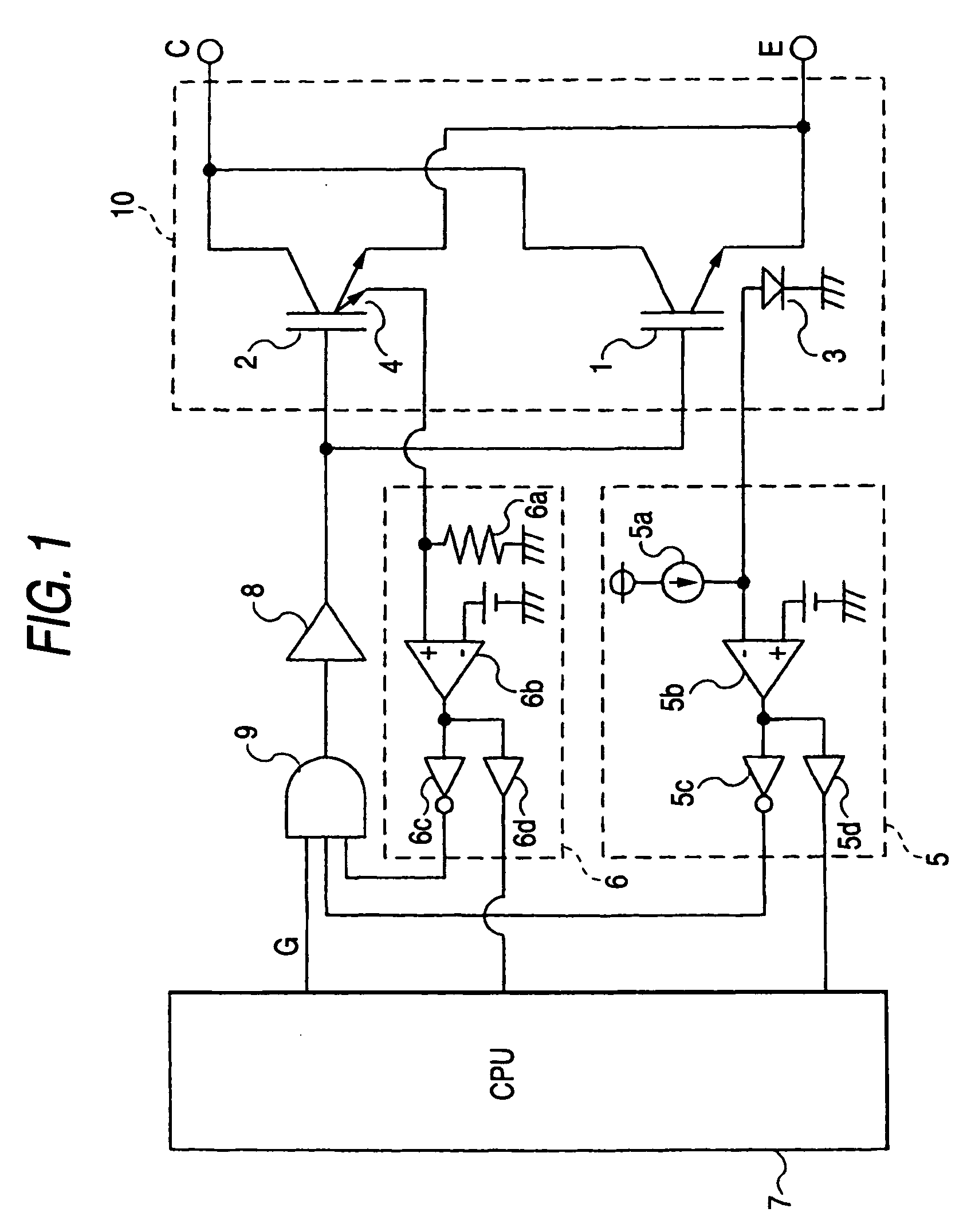
[0019]FIG. 1 is a circuit diagram of a semiconductor power converter apparatus according to Embodiment 1 of the invention. Here, an IGBT module in which two IGBTs are connected in parallel is shown as a semiconductor power conversion circuit 10, which is provided with a collector terminal C, an emitter terminal E, and a gate signal terminal G as its external terminals. An IGBT 1 has a temperature sensing diode 3 for detecting the temperature of the IGBT 1, and an IGBT 2 has a current sensing cell 4 for detecting the current of the IGBT 2. These IGBTs 1 and 2 are mounted on a same heatsink (not shown).

[0020]An overheat protection circuit 5 includes a constant current source 5a for causing the temperature sensing diode 3 to generate a forward voltage, an overheat determining comparator circuit 5b for comparing the forward voltage of the temperature sensing diode 3 with a predetermined reference voltage value, a logic inverter circuit 5c for turning off the IGBT 1 and the IGBT 2 if the...

embodiment 2

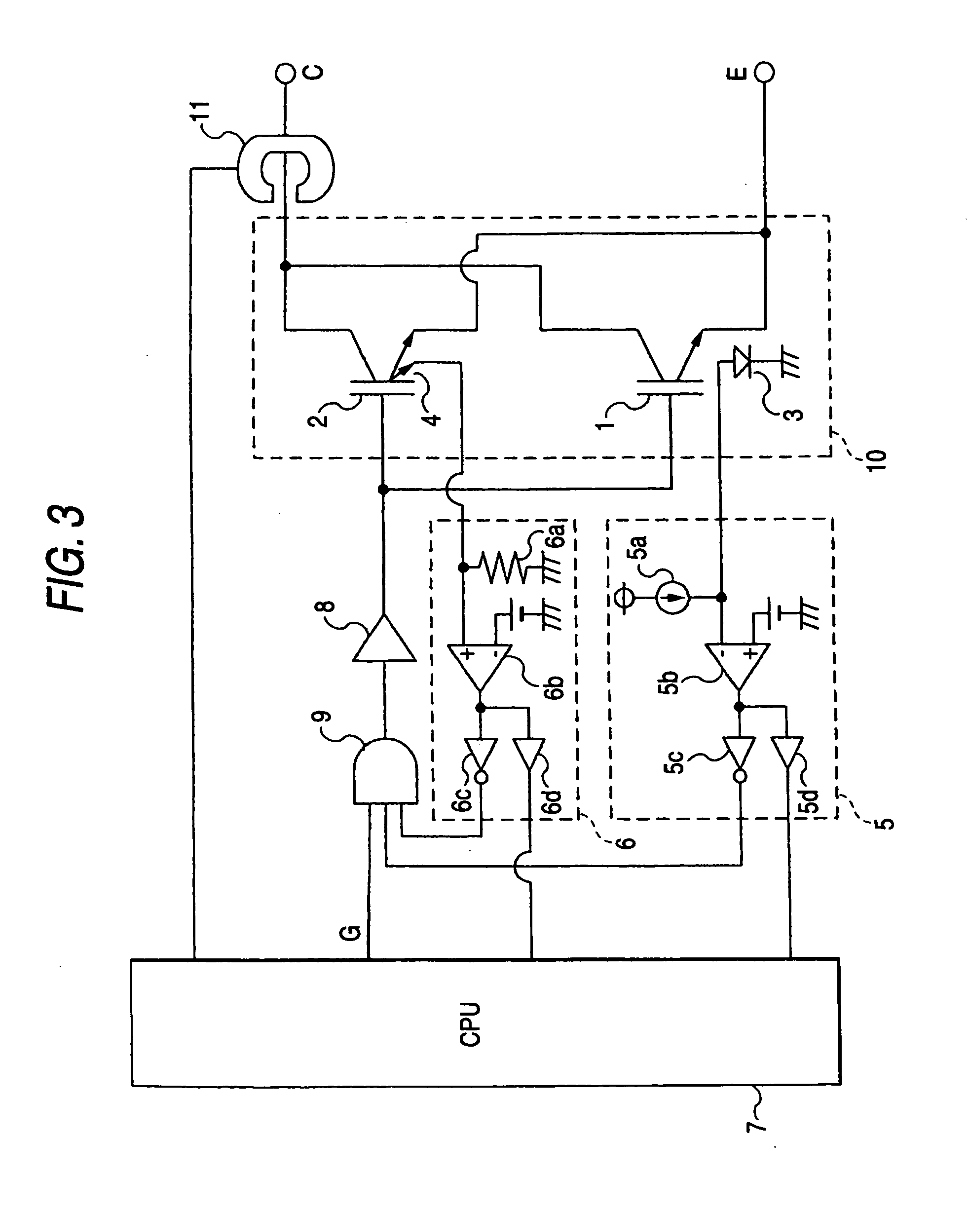
[0035]FIG. 3 is a circuit diagram of a semiconductor power converter apparatus according to Embodiment 2 of the invention, which attains a semiconductor power converter apparatus with higher reliability and higher redundancy by detecting the output current of the semiconductor power conversion circuit 10.

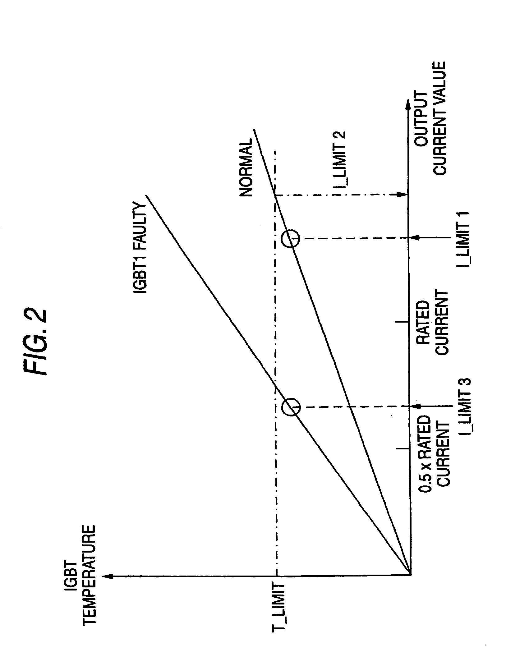
[0036]Referring to FIG. 3, a current sensor 11 detects the output current of the semiconductor power conversion circuit 10, which is the total current of the IGBT 1 and the IGBT 2. The output of the current sensor 11 is input into a CPU 7. When the overcurrent protection circuit 5 or the overheat protection circuit 6 operates, the CPU 7 compares the detected value by the current sensor 11 with a predetermined set value during the protection operation.

[0037]At this time, if both the IGBTs are in a normal condition, the output value from the current sensor shows a greater value than I_limit1, while if either of the IGBTs undergoes an open failure, the output value shows a value about ...

embodiment 3

[0044]FIGS. 6 and 7 are a circuit diagram of a three phase inverter device according to Embodiment 3 of the invention and a layout diagram of IGBTs that form inverter bridges, respectively.

[0045]Referring to FIG. 6, a three phase inverter circuit 12 comprises three sets of IGBT modules 1a, 1b, and 1c each including two IGBTs each having a temperature sensing diode 3, and three sets of IGBT modules 2a, 2b, and 2c each including two IGBTs each having a current sensing cell 4, and it converts DC power supplied from a battery 13 into AC power.

[0046]Each of the bridge arms of the three phase inverter circuit 12 is formed by connecting the IGBTs of the IGBT modules 1a, 1b, and 1c with the IGBTs of the IGBT modules 2a, 2b, and 2c in parallel one by one, and each of the IGBTs connected in parallel is provided with an overheat protection circuit 5 and an overcurrent protection circuit 6, as illustrated in Embodiment 1.

[0047]Furthermore, as illustrated in FIG. 7, the IGBT modules 1a, 1b, 1c a...


PUM


Abstract

Even when one of IGBTs fails in a semiconductor power converter apparatus in which a plurality of semiconductor elements are connected in parallel, the remaining IGBT(s) is prevented from failing with a simple circuit configuration. The semiconductor power converter apparatus includes: a semiconductor power conversion circuit in which a first IGBT having a temperature sensing unit and a second IGBT having a current sensing unit are connected in parallel, for causing the first and second semiconductor elements to perform switching operations; an overheat protection circuit for performing overheat protection for the first and second IGBTs based on temperature information obtained from the temperature sensing unit of the first IGBT; and an overcurrent protection circuit for performing overcurrent protection for the first and second IGBTs based on current information obtained from the current sensing unit of the second IGBT.

Description

BACKGROUND OF THE INVENTION[0001]1. Field of the Invention[0002]This invention relates to a semiconductor power converter apparatus in which a plurality of semiconductor elements are connected in parallel.[0003]2. Description of Related Art[0004]In a semiconductor power converter apparatus using power semiconductor elements, such as represented by IGBTs (Insulated Gate Bipolar Transistors), the IGBTs are caused to perform switching operations and the proportions of the current passing therethrough are controlled, to adjust the electric power flow. Passage of an overcurrent through such a semiconductor power converter apparatus elevates the temperature of the IGBTs, which may result in destruction of the semiconductor power converter apparatus. A variety of protection circuits for preventing the IGBTs from the destruction have been proposed which detects the temperature of the IGBTs with a temperature sensing unit to stop the operation of the IGBTs or to limit the passing current thr...

Claims


Application Information

Patent Timeline
Patent Type & Authority Applications(United States)
IPC IPC(8): H01L23/62
CPCH01L23/34H01L25/18H02M1/32H02M7/538H03K17/0828H03K17/127H01L2924/0002H03K17/18H03K2017/0806H01L2924/00
Inventor OKUDA, TATSUYAMICHINAKA, TAKUYA
Owner MITSUBISHI ELECTRIC CORP
Why Eureka
Try Eureka