Gear/Drive Unit

a gear/drive unit and gear technology, applied in the direction of gearing, hoisting equipment, roofs, etc., can solve the problems of bending the gear housing open, affecting the strength of the gear housing, and requiring more expensive rework steps

Inactive Publication Date: 2007-12-20
ROBERT BOSCH GMBH
View PDF8 Cites 5 Cited by
  • Summary
  • Abstract
  • Description
  • Claims
  • Application Information

AI Technical Summary

Benefits of technology

[0007] In this case, a gear drive unit is provided, particularly for a seat adjuster or a power-assisted steering system, which is fastened on a base part and is comprised of a spindle, on which a drive gear that drives the spindle is provided, a drive assembly, which drives the drive gear by means of a driven element and at least one device on which the drive assembly is at least flanged-mounted and which operationally couples at least the driven element and the drive gear, wherein at least one additional support is provided in which the drive gear is mounted, and this support is fastened to the base part and supports the device.
[0008] A more compact and simpler structure is achieved which can absorb high crash forces if the support has at least the shape of a tube, and at least a first bearing cap is provided, which is fastened in the support and positions the drive gear axially and radially on one side.
[0009] The arrangement is then completed in that a second bearing cap is provided, which is fastened in the support and positions the drive gear axially and radially on the other side, or that the support has the shape of a pot and positions the drive gear axially and radially on the other side.
[0010] The support preferably has at least one radial recess, through which the driven element of the drive assembly and the drive gear are connected to one another. This produces the furthest possible closed structure of the support, whereby high crash forces can be absorbed.
[0011] A particularly simple method for assembling is produced in that the spindle, the drive gear and the support form a first main assembly, that the driven element, the drive assembly and the device form a second main assembly and that the first and second main assemblies are each assembled separately first and then fit together. In this case, the axial play of the drive gear is minimized during assembly by pushing together the drive gear and the support and at least one bearing cap.
[0012] Additional advantages and advantageous developments are yielded from the subordinate claims and the description.

Problems solved by technology

In general, the metal housing required for this necessitates more expensive rework steps in order to comply with tolerances.
In this case, a lateral opening that is designed to be vertical to the spindle axis for inserting the spindle has a fundamentally negative effect on the strength of the gear housing, i.e., the gear housing tends to bend open under tensile loads.
As a result, this often requires a new gear housing for each application.

Method used


Image

  • Gear/Drive Unit
  • Gear/Drive Unit
  • Gear/Drive Unit

Examples


Embodiment Construction

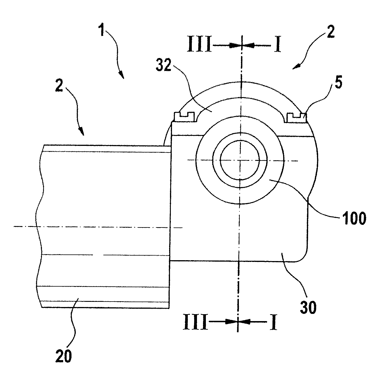
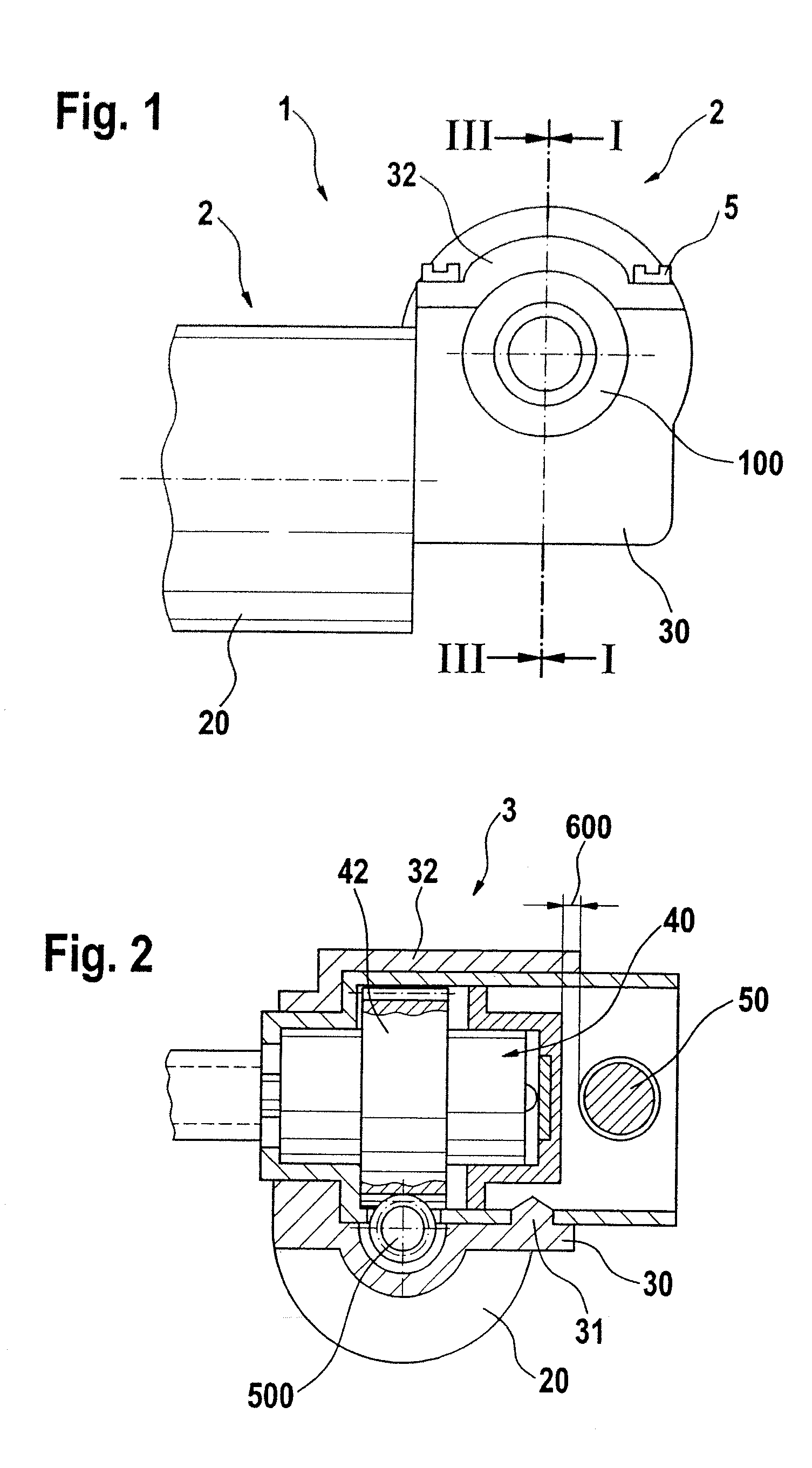
[0019] The spindle drive 1 depicted in FIGS. 1 and 2 is comprised of two main assemblies 2, 3 with different functions. The first main assembly 2 includes a drive assembly 20, e.g., an electric motor, with a worm 500, a gear housing 30 and the gear cover 32. This assembly 2 is used to accommodate and drive the second main assembly 3.

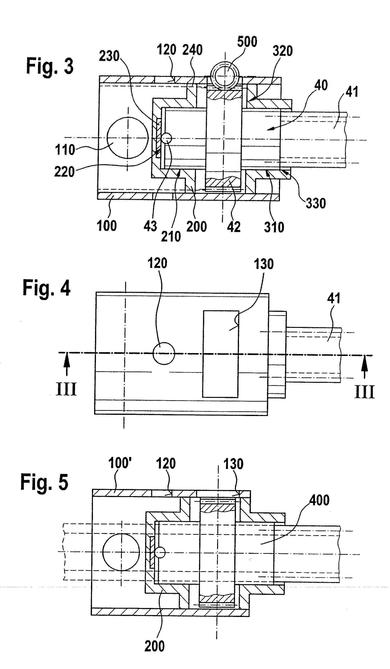
[0020] The second main assembly 3 represents a spindle module. It forms an interface, positions the worm wheel, and supports the operating forces and crash forces. The passive functions, i.e., supporting crash forces, are fulfilled without the help of the first main assembly 2. The second main assembly 3 includes a tubular support 100, wherein the profile of the tube can be embodied in different ways, e.g., round, flattened, rectangular, etc. The support 100 can be manufactured using different fabrication methods, e.g., rolled, drawn, cast, etc.

[0021] According to FIGS. 3 through 5, areas 110, 120, 130 with different functions that are depicted here as...


PUM

PropertyMeasurementUnit
shapeaaaaaaaaaa
circumferenceaaaaaaaaaa
frictionaaaaaaaaaa

Abstract

The invention relates to a gear drive unit (10)5, particularly for a seat adjuster or a power-assisted steering system, comprised of a spindle (40), on which a drive gear (42) that drives the spindle (40) is provided, a drive assembly (20), which drives the drive gear (42) by means of a driven element (500) and at least one device (30) on which the drive assembly (10)6 is at least flanged-mounted, and which operationally couples at least the driven element (500) and the drive gear (42). The invention provides that at least one additional support (100, 100′) is provided in which the drive gear (42) is mounted, and this support is fastened to the base part (50) and supports the device (30). 5 Translator's note: [sic] This appears to be a typographical error. The gear drive unit is designated “(1)” elsewhere in the document. 6 Translator's note: [sic] This appears to be a typographical error. The drive assembly is designated “(20)” elsewhere in the document.

Description

PRIOR ART [0001] The invention relates to a gear drive unit, particularly for a seat adjuster or a power-assisted steering system in a motor vehicle, in accordance with the species of the main claim. [0002] A device for adjusting a seat in a motor vehicle in known from EP 0 759 374 or DE 43 31 822, which is fastened on a base part, and is comprised of a spindle on which a drive gear that drives the spindle is provided, a drive assembly, which drives the drive gear by means of a driven element and at least one device on which the drive assembly is at least flanged-mounted and which operationally couples at least the driven element and the drive gear. [0003] In the case of a seat adjuster motor with a spindle drive, a spindle is inserted into a gear housing, which is generally already connected to a motor. The inserted spindle is often executed as a composite part and is comprised in the simplest case of the spindle, a sprayed-on worm wheel and an axial point abutment, which is execut...

Claims


Application Information

Patent Timeline
Patent Type & Authority Applications(United States)
IPC IPC(8): F16H13/00
CPCB60N2/0232F16H1/16Y10T74/19642Y10T29/49464B60N2002/0236B60N2/02253B60N2/02246B60N2/02B62D5/04
Inventor OBERLE, HANS-JUERGENSCHMIDT, WILLILIENIG, ANDREAS
Owner ROBERT BOSCH GMBH
Why Eureka
Try Eureka