Vehicle switch

Active Publication Date: 2007-12-20
PANASONIC CORP
View PDF6 Cites 17 Cited by
  • Summary
  • Abstract
  • Description
  • Claims
  • Application Information

AI Technical Summary

Benefits of technology

[0012]The present invention is a simply structured vehicle switch allowing an electrical switch-on or switch-off with reliability. The vehicle switch of the present invention includes a magnet mounted to an operating unit accommodated in an external packaging such that the operating unit can move linearly ; and a magnetic detector sensible magnetism of the magnet, so that a switching device can be opened or closed in response to strength of the detected magnetism.

Problems solved by technology

As a result, carbide or silicon compound is formed on the surface of contacts 3 and 4, thereby inviting failure in electri

Method used


Image

  • Vehicle switch
  • Vehicle switch
  • Vehicle switch

Examples


Example

First Exemplary Embodiment

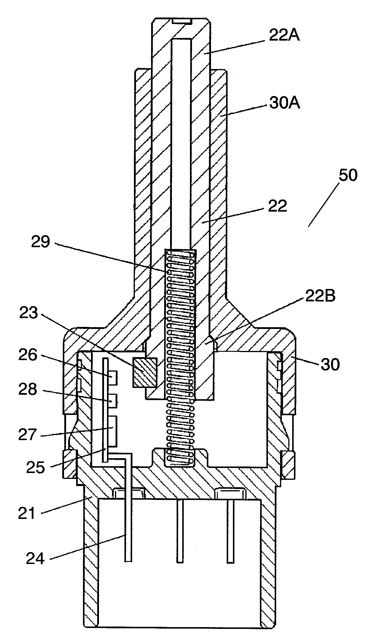
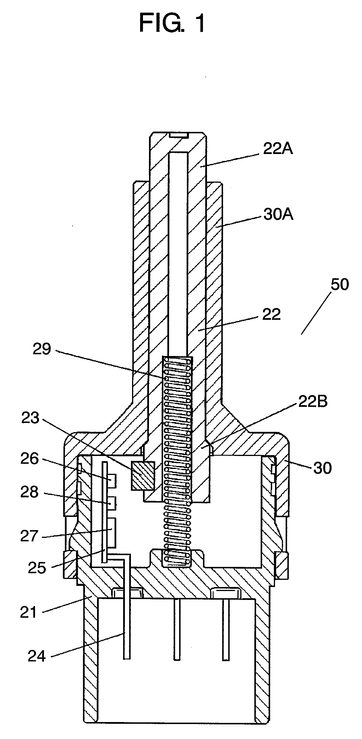
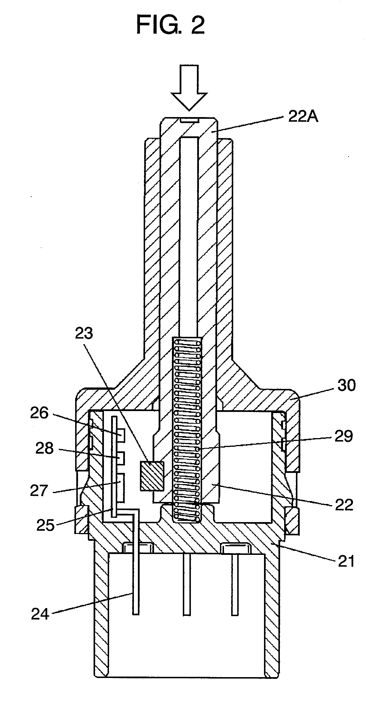
[0028]FIGS. 1 and 2 show sectional views of a s vehicle witch in accordance with the first exemplary embodiment of the present invention. FIG. 1 shows a steady state and FIG. 2 shows an operated state thereof. FIG. 3 shows a lateral view of brake employing the vehicle switch shown in FIG. 1. Housing 21 and cover 30 form the external packaging of vehicle switch 50. Housing 21 is box-shaped having an opening at the top thereof, and is made of insulating resin, e.g. polybutylene terephthalate (PBT) or acrylonitrile-butadien-styrene (ABS). Cover 30 covers the opening at the top of housing 21. Substantially columnar operating unit 22 made of insulating resin can move upward and downward in the external packaging made of housing 21 and cover 30 along cylinder 30A. That is to say, operating unit 22 is accommodated in the external packaging so as to be movable linearly.

[0029]Magnet 23 is attached to a lower lateral face of operating unit 22. Terminals 24 made of me...

Example

Second Exemplary Embodiment

[0039]FIG. 6 shows a sectional view of a vehicle switch in accordance with the second exemplary embodiment of the present invention. This vehicle switch has basically a similar structure to the structure in accordance with the first exemplary embodiment shown in FIG. 1 except that the switch has additional switch contact 34, which are formed of movable contact 34A and fixed contact 34B. Movable contact 34A made of thin metal plate such as copper alloy is fixed to the lower right side of operating unit 22 at its first end. Two of fixed contacts 34B made of, e.g. copper alloy, are placed on the right-side inner wall of housing 21. The second end of movable contact 34A is somewhat bowed and brought into contact with fixed contacts 34B, so that they are electrically connected to each other.

[0040]Switch contact 34 is coupled to a wired pattern of wiring board 25 via arms (not shown) extending from fixed contacts 34B. FIG. 8 shows the circuit diagram of the enti...

Example

Third Exemplary Embodiment

[0052]FIG. 9 shows a sectional view of a vehicle switch in accordance with the third exemplary embodiment of the present invention. This vehicle switch has basically a similar structure to the structure in accordance with the first exemplary embodiment and shown in FIG. 1 except that the switch additionally includes adjuster 33 made from insulating resin such as polybutyleneterephthalate (PBT) or polyurethane. Adjuster 33 has a sectional view shaped like letter “T” and is provided on the tip of operating unit 22. Namely, operating unit 22 has adjuster 33 for adjusting the whole length of operating unit 22 at its end protruding from cover 30 which is a part of the external packaging.

[0053]More specifically, adjuster 33 is provided at the tip of operating unit 22 protruding upwardly from the cylindrical portion at the center on the top face of cover 30. Adjuster 33 is provided to adjust the position of upper end of operating unit 22, and has pushing section 3...


PUM


Abstract

A vehicle switch includes a magnet mounted to an operating unit accommodated in an external packaging such that the operating unit can move linearly. A magnetic detector is placed so as to receive different strength of the magnetism from the magnet in the two cases that the operating unit is at the upper limit position and at the lower limit position. A control circuit coupled to the magnetic detector opens and closes a switching device in response to strength of the detected magnetism.

Description

BACKGROUND OF THE INVENTION[0001]1. Field of the Invention[0002]The present invention relates to switches to be used for turning on or off brake lights in response to stepping on the brake pedal of a vehicle.[0003]2. Background Art[0004]A push-type vehicle switch has been widely used for controlling brake lights in response to stepping on the brake pedal of a vehicle, to be more specific, the push switch turns on the brake lights when a driver steps on the brake pedal, and turns off the brake lights when the driver releases the pedal. Such a conventional vehicle switch is described hereinafter with reference to FIGS. 14 and 15.[0005]FIG. 16 shows a sectional view of a conventional vehicle switch. This vehicle switch has housing 1 made of insulating resin, shaped like a box, and open upward; and operating unit 2 accommodated in housing 1 and movable vertically. Operating shaft 2A of operating unit 2 slides along cylinder 7A of cover 7 covering the opening at the top of housing 1. A p...

Claims


Application Information

Patent Timeline
IPC IPC(8): H02P7/00
CPCH01H36/02H01H3/16
Inventor SHIMIZU, MASARUSASANOUCHI, KIYOTAKAKOSAKA, HIROYUKIMAEDA, TSUTOMU
Owner PANASONIC CORP
Why Eureka
Try Eureka