
Multi-domain liquid crystal display

a liquid crystal display and multi-domain technology, applied in non-linear optics, instruments, optics, etc., can solve the problems of deterioration of visibility of reflection type lcd devices in dark surroundings, insufficient panel brightness, and often insufficient fringe fields generated by slit formation, etc., to achieve easy formation, reduce the area of disclination, and strengthen the field strength

Inactive Publication Date: 2007-12-20
WINTEK CORP +1
View PDF13 Cites 8 Cited by
  • Summary
  • Abstract
  • Description
  • Claims
  • Application Information

AI Technical Summary

Benefits of technology

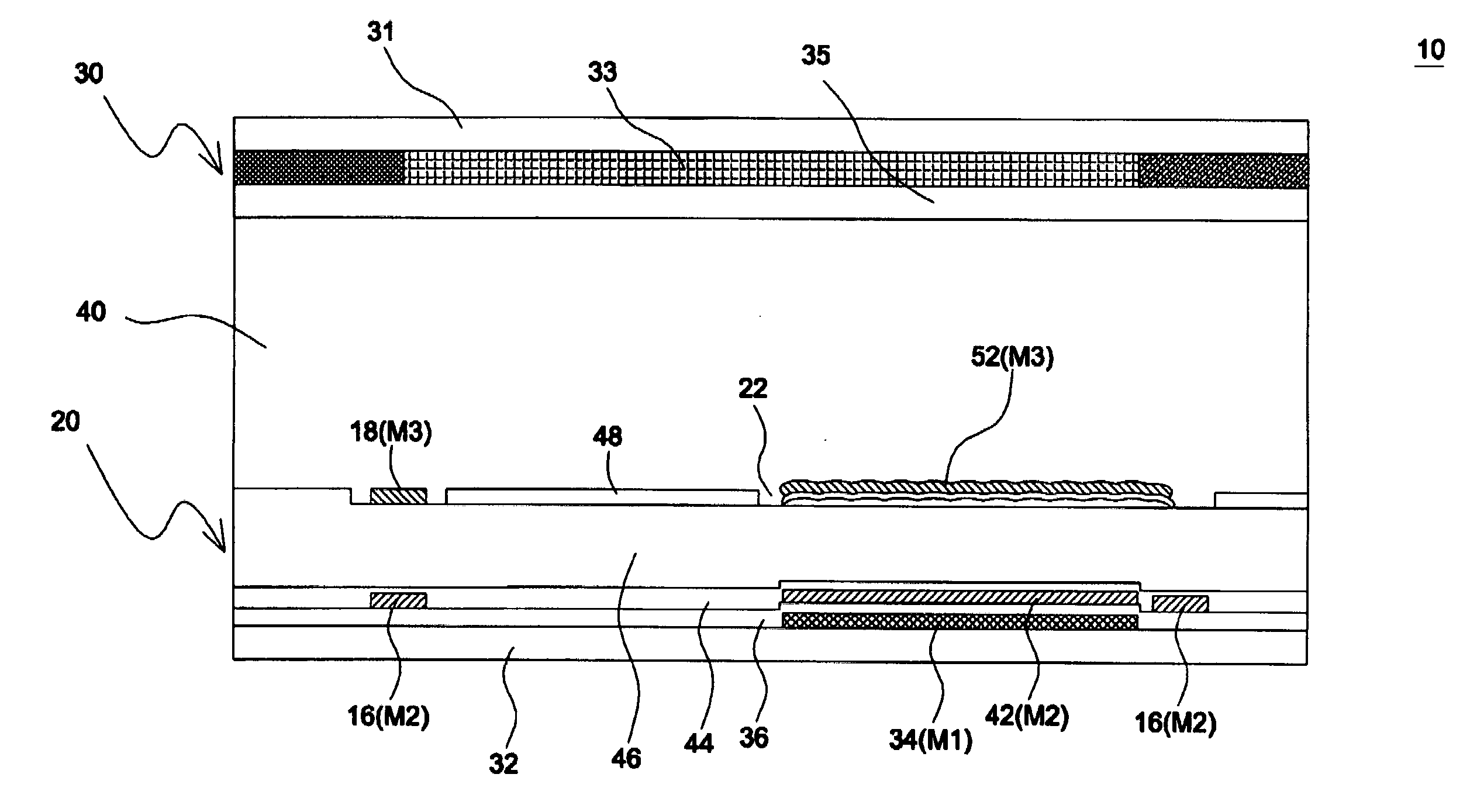
[0013] Through the design of the invention, a multi-domain profile of a liquid crystal cell is easily formed by providing auxiliary electrodes, which are formed through typical TFT fabrication processes and have an opposite polarity in relation to adjacent pixel electrode to produce fringe fields. Hence, compared with the conventional design where a protrusion or a via structure is used to cause tilted liquid crystal molecules, the residue phase difference is eliminated to avoid light leakage since all liquid crystal molecules are vertically aligned under a field-off state. Further, compared with another conventional design where only slits are formed to produce fringe fields, the biased auxiliary electrode allows for stronger field strength to tilt liquid crystal molecules so as to reduce the area of a disclination region and thus increase the light-transmittance of a LC cell having both a transmissive region and a reflective region. In addition, according to the invention, the storage capacitor formed in each picture element overlaps with signal lines or is positioned underneath reflective electrodes to further improve the pixel aperture ratio.

Problems solved by technology

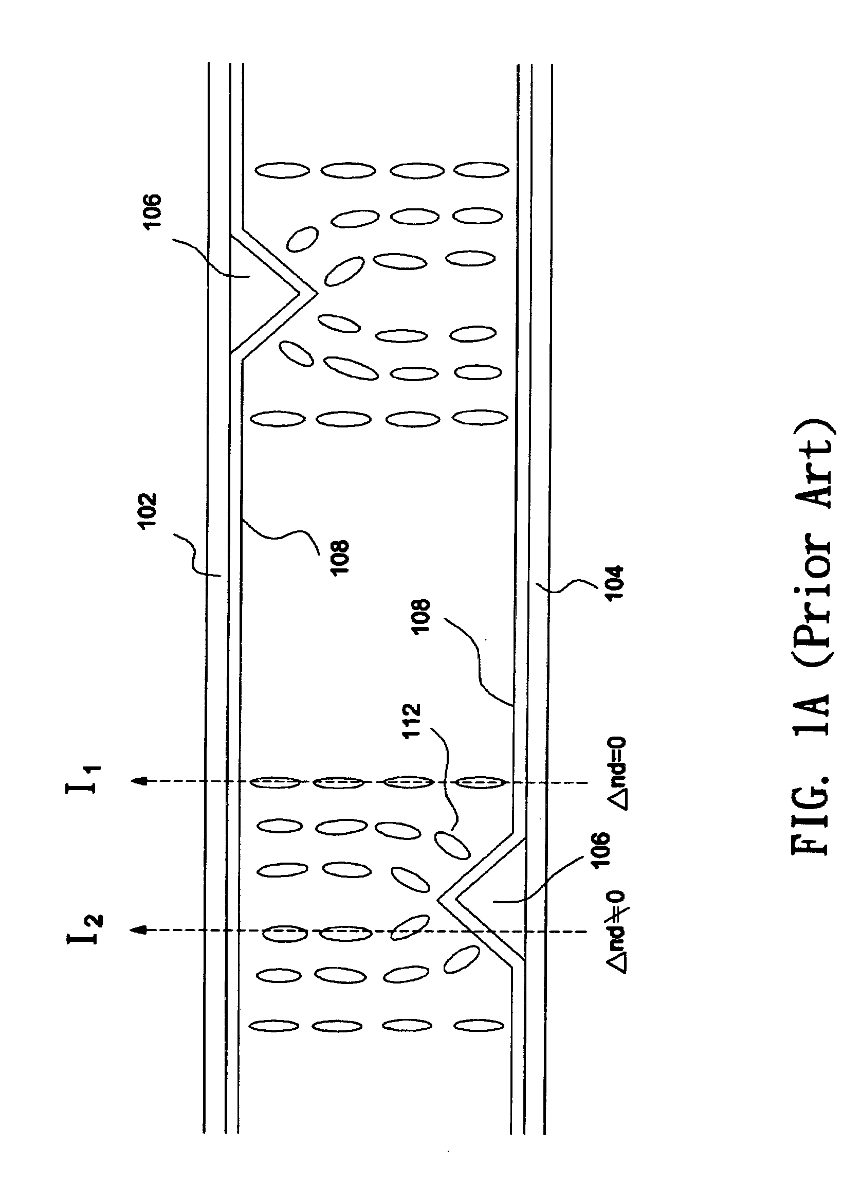
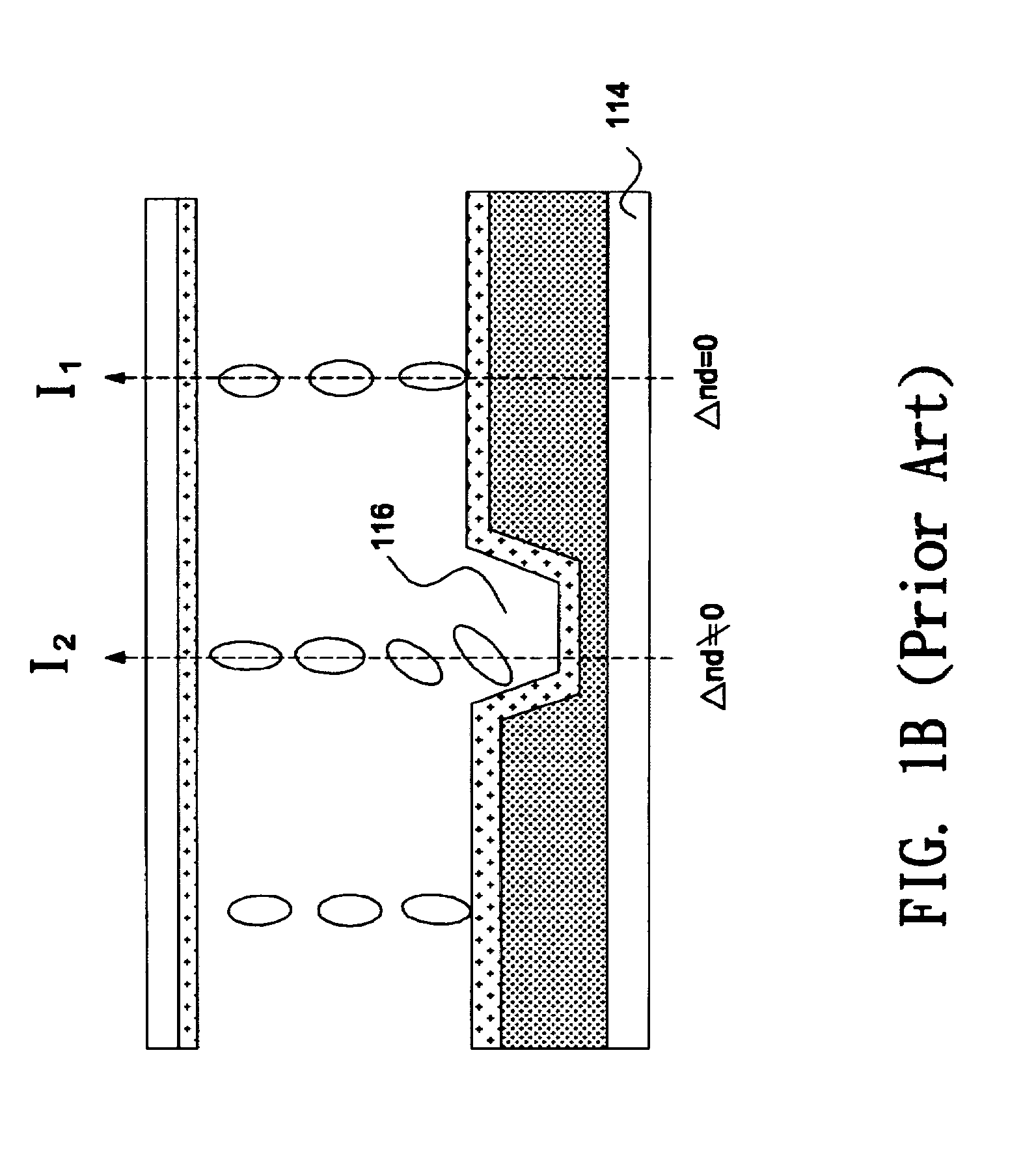
However, the strength of the fringe fields generated by the formation of the slits 206 is often insufficient, particularly when the widths and the intervals of the slits 206 are not optimized.
Moreover, in a transmission type LCD device, a backlight is used to obtain a bright display independent of surrounding environments, and thus the panel brightness is often not sufficient when the device is exposed to direct sunlight.
In comparison, in a reflection type LCD device, surrounding light is employed to effect a display, so that the backlight source can be omitted; however, the reflection type LCD device is largely deteriorated in visibility in a dark surrounding.

Method used


Image

  • Multi-domain liquid crystal display
  • Multi-domain liquid crystal display
  • Multi-domain liquid crystal display

Examples


Embodiment Construction

[0030]FIGS. 3A and 3B show schematic diagrams illustrating a multi-domain liquid crystal display 10 according to an embodiment of the invention, where FIG. 3A is a top view observed from the normal direction of an array substrate, and FIG. 3B is a cross-section taken along line A-A′ in FIG. 3A.

[0031] Referring to FIG. 3A, a plurality of picture elements 12 that constitute the multi-domain liquid crystal play 10 are shown. Herein, the term “picture element” indicates a minimum addressable unit of a display such as a red (R), green (G), or blue (B) sub-pixel of a color liquid crystal play. A plurality of scan lines 14 are arranged extending in the horizontal direction, and a plurality of data lines 16 are arranged extending in a vertical direction, with each two scan lines 14 intersected with two data lines 16 to define a pixel area on which a picture element 12 is spread. Each picture element 12 includes a transmissive region 121 and a reflective region 122 (indicated by hatched lin...


PUM


Abstract

A multi-domain liquid crystal display includes multiple first and second picture elements and multiple first and second auxiliary electrodes. The first and second picture elements have opposite polarities under the same frame of an inversion drive scheme, and each picture element has a reflective region and a transmissive region. The first auxiliary electrodes are connected to the first picture elements, and each of the first auxiliary electrodes is positioned next to at least one side of one second picture element. The second auxiliary electrodes are connected to the second picture elements, and each of the second auxiliary electrodes is positioned next to at least one side of one first picture element.

Description

BACKGROUND OF THE INVENTION [0001] (a) Field of the Invention [0002] The invention relates to a multi-domain liquid crystal display and, more particularly, to a multi-domain liquid crystal display having both transmissive regions and reflective regions. [0003] (b) Description of the Related Art [0004] Typically, the display contrast ratio and response speed offered by a vertically aligned (VA) mode liquid crystal display (LCD), which uses negative liquid crystal materials and vertical alignment films, are better than a twisted-nematic (TN) mode LCD, since liquid crystal molecules are aligned in a vertical direction when no voltage is applied. Also, it is known the viewing angle performance of a VA mode LCD is improved by setting the orientation directions of the liquid crystal molecules inside each picture element to a plurality of mutually different directions; that is, forming multiple distinct domains in the liquid crystal display. [0005]FIG. 1A shows a schematic diagram illustra...

Claims


Application Information

Patent Timeline
IPC IPC(8): G02F1/1337
CPCG02F1/1393G02F1/133707
Inventor WANG, WEN-CHUNLIU, CHIN-CHANGWANG, I FANGYU, MING-CHANG
Owner WINTEK CORP
Learn More