Light -Emitting Body,Lighting Device And Display Device Using The Same

a technology of light-emitting body and display device, which is applied in the direction of indium organic compound, transportation and packaging, coating, etc., can solve the problems of poor color rendering properties, complication of the system, and inferior color rendering properties of the combination, and achieve the effect of wide directivity

Inactive Publication Date: 2007-12-20
SHOWA DENKO KK
View PDF7 Cites 16 Cited by
  • Summary
  • Abstract
  • Description
  • Claims
  • Application Information

AI Technical Summary

Benefits of technology

[0090] Furthermore, in a range that does not disturb effects of the invention, various kinds of additives can be appropriately added to the resin composition. Examples of additives include heat resistant stabilizers, hindered phenols and phosphorus antioxidants, organic lubricants, fluidity-controlling agents and adhesiveness-imparting agents such as silane coupling agents. Examples of the silane coupling agent include KBM303, KBM403 and KBM402 (product codes: manufactured by Shin-Etsu Silicone Co., Ltd.).
[0091] Still furthermore, when necessary, existing known additives such as silicone-based, fluorinated or polymer-based defoaming agent; leveling agent; silicone-based or acrylic pigment-dispersing agent; flame retardents such as antimony trioxide, bromo compound, phosphate ester, red phosphorus and nitrogen-containing compound such as melamine resin; and a stress relaxation agent such as silicone oil and silicone rubber powder can be used. Furthermore, in order to impart wide directivity, a diffusing agent such as calcium carbonate, resin beads and spherical silica may be contained to diffuse light.
[0092] A method of manufacturing the light-emitting device according to the invention includes a step of obtaining a composition by adding an iridium complex into a binder followed by mixing through stirring; a step of covering a gallium nitride compound semiconductor with the medium containing the iridium complex; and a step of fixing the medium containing the iridium complex.
[0093] When the binder is, for instance, an epoxy resin, the manufacturing method includes a step of obtaining a composition by adding an iridium complex to an epoxy resin followed by mixing through stirring; a step of covering a gallium nitride compound semiconductor with the epoxy resin containing the iridium complex; and a step of curing the epoxy resin containing the iridium complex.
[0094] The method of adding an iridium complex to an epoxy resin and mixing the resin composition through stirring is not particularly restricted; however, the step can be carried out by mixing the resin composition with a shaker at room temperature. At this time, the process may be carried out under heating. The mixture may be heated to a temperature lower than the curing temperature for a short time, or after the mixing of the base material resin (so-called main ingredient) alone, a curing agent may be added.
[0095] It is preferable that the binder thus obtained containing iridium complex be deaerated before the subsequent steps. Deaerating method is not particularly restricted. For instance, deaeration can be carried out by placing the binder containing iridium complex in a desiccator and maintaining it under reduced pressure for 10 to 300 minutes.

Problems solved by technology

However, the cold cathode tube is narrow in the color reproduction range and poor in the color rendering properties, and furthermore use of mercury involves problems in light of environmental protection.
However, the system does not contain genuine green and red components in the light source; accordingly, there are problems in that the combination is inferior in the color rendering properties as lighting and is narrower in the color reproduction range when it is used as a backlight of a display.
However, since three light-emitting diodes have to be used, three power supplies and control systems are required, which leads to complication of the system.
However, in the method, the photo-deterioration of constituent members due to UV-light cannot be avoided; accordingly, it does not have the lifetime practically sufficient as a light source.
In this case, there are problems in that separation tends to occur at the interface between the powder and the resin, which results in inferior durability, and that difference in the refractive indices between the powder and the resin, causing generation of hiding power in some cases of certain powder concentration and certain particle size distribution, hinders obtaining high brightness.

Method used


Image

  • Light -Emitting Body,Lighting Device And Display Device Using The Same
  • Light -Emitting Body,Lighting Device And Display Device Using The Same
  • Light -Emitting Body,Lighting Device And Display Device Using The Same

Examples


example 1

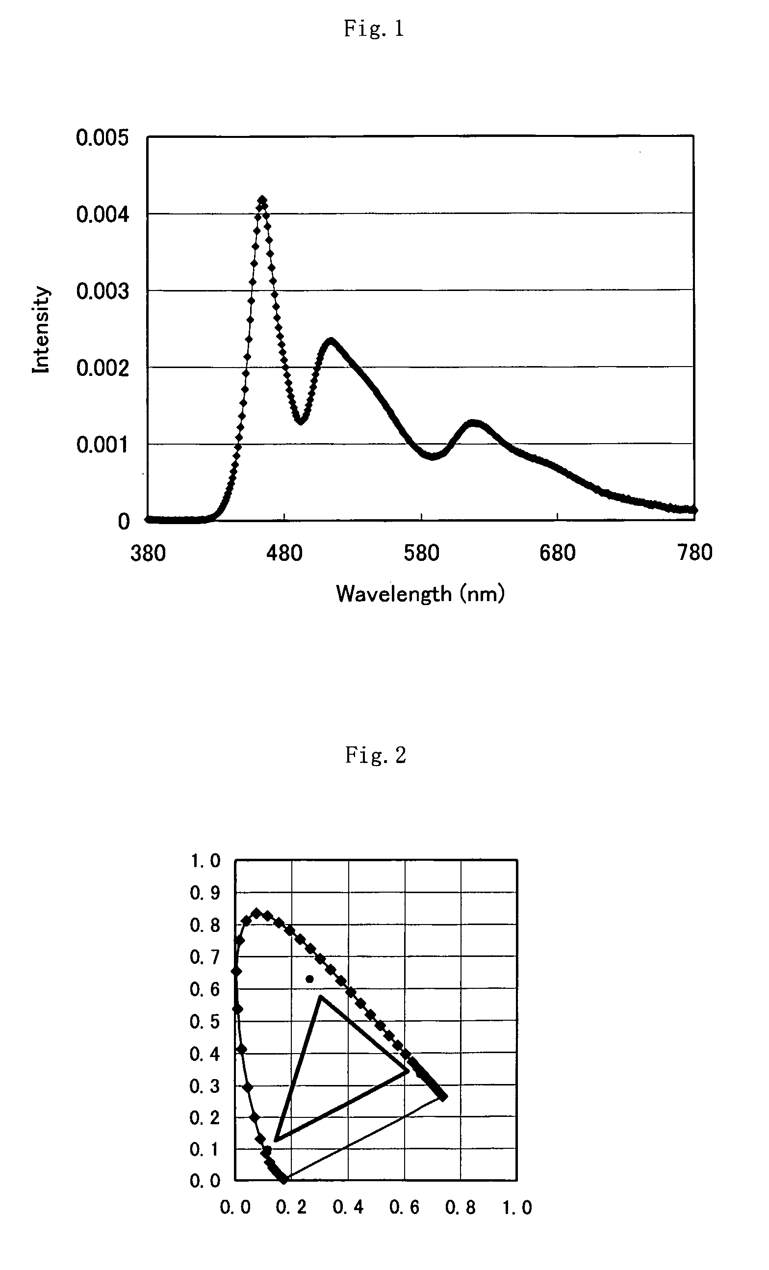
[0138] A secondary luminescent unit was prepared by adding 9 mg of an iridium complex (E2) and 1 mg of an iridium complex (E17) into a mixture of 5 g of bisphenol A diglycidyl ether and 5 g of methylhexahydrophthalic anhydride. After mixing the materials, the mixture was defoamed. Thus obtained mixture was poured into a recess portion of a cup of a lead frame in which a blue light-emitting diode serving as a primary luminescent unit was disposed and cured at 120° C. for 1 hour. Furthermore, into a mold form for a lamp-type (bombshell type), a mixture of bisphenol A diglycidyl ether and methylhexahydrophthalic anhydride was poured in advance, and then the lead frame was immersed, followed by curing at 120° C. for 1 hour, to thereby prepare a lamp-type white LED. With respect to the obtained white LED, the x and y chromaticity coordinates, the color rendering index, the initial luminous efficiency and a decrease in the luminous efficiency after 100-hour operation were measured. Result...

example 2

[0139] A lamp-type LED was prepared in the same manner as in Example 1 except that 8.9 mg of a complex (E1) and 1.1 mg of a complex (E16) were used as the iridium complex. With respect to the obtained white LED, the x and y chromaticity coordinates, the color rendering index, the initial luminous efficiency and a decrease in the luminous efficiency after 100-hour hr operation were measured. Results thereof are shown in Table 1.

example 3

[0140] A lamp-type LED was prepared in the same manner as in Example 1 except that 9.1 mg of a complex (E3) and 0.9 mg of a complex (E18) were used as the iridium complex. With respect to the obtained white LED, the x and y chromaticity coordinates, the color rendering index, the initial luminous efficiency and a decrease in the luminous efficiency after 100-hour hr operation were measured. Results thereof are shown in Table 1.


PUM

PropertyMeasurementUnit
wavelengthaaaaaaaaaa
emission peakaaaaaaaaaa

Abstract

A light-emitting body comprising a primary luminescent unit and a secondary luminescent unit that emits light owing to light emitted from the primary luminescent unit, wherein the secondary luminescent unit contains an iridium compound. As the iridium compound, an iridium complex represented by L1L2L3Ir, (L1, L2 and L3 are organic bidentate ligands coordinated to iridium, and at least one of these ligands coordinates with a nitrogen atom and a carbon atom) preferably, represented by formula (2) can be cited. (In the formula, X represents an atom group that forms an aromatic chelate ligand together with a carbon atom and a nitrogen atom bonded with iridium, n is an integer of 2 or 3, and L represents a bidentate organic ligand wherein the atoms other than carbon atoms are bonded with iridium.) The light-emitting body of the invention contains red (R), green (G) and blue (B) wavelength components to be wide in the color reproduction range, can be driven with a single power supply and control system, and does not cause photo-deterioration of constituent members.

Description

CROSS-REFERENCE TO RELATED APPLICATIONS [0001] This is an application filed pursuant to 35 U.S.C. Section 111(a) with claiming the benefit of U.S. provisional application Ser. No. 60 / 608,099 filed Sep. 9, 2004, U.S. provisional application Ser. No. 60 / 619,716 filed Oct. 19, 2004, U.S. provisional application Ser. No. 60 / 622,608 filed Oct. 28, 2004 and U.S. provisional application Ser. No. 60 / 690,915 filed Jun. 16, 2005 under the provision of 35 U.S.C. 111(b), pursuant to 35 U.S.C. Section 119(e)(1).TECHNICAL FIELD [0002] The present invention relates to a light-emitting body that uses an organic fluorescent dye, is excellent in the luminous efficiency and color rendering properties and long in the lifetime, and lighting and display devices using the same. BACKGROUND ART [0003] Conventionally, as a light source of a lighting device or a non-self-luminous type display device, a cold cathode tube or a light-emitting diode has been used. However, the cold cathode tube is narrow in the c...

Claims


Application Information

Patent Timeline
Patent Type & Authority Applications(United States)
IPC IPC(8): C09K11/06H01L51/30H05B33/14H01L33/32H01L33/48
CPCC09K11/06C09K2211/1007C09K2211/1011C09K2211/1029C09K2211/1033C09K2211/1037Y10T428/10C09K2211/1092C09K2211/185H01L33/502H01L51/0085H05B33/14C09K2211/1044H01L2224/48091H01L2224/48227H01L2224/45139H01L2924/00011C09K2323/00H01L2924/00014H10K85/342H01L2924/00H01L2924/01048H01L2224/45015H01L2924/207H01L2924/01049C07F15/0033H10K50/00
Inventor SHINOZAKI, KENJIHANAWA, KENZOTAKAHASHI, YOSHIAKIKATO, TSUYOSHIWATANABE, TAKEO
Owner SHOWA DENKO KK
Why Eureka
Try Eureka