Method For Double Sampling Loop Negative Feedback And Double Sampling Negative Feedback Amplifier

a loop negative feedback and amplifier technology, applied in the field of amplifiers, can solve the problems of limited loop negative feedback capability to lower amplifier distortion, further increase in feedback depth, etc., and achieve the effect of increasing feedback depth

Inactive Publication Date: 2007-12-27
ZHOU ZONGSHAN
View PDF7 Cites 7 Cited by
  • Summary
  • Abstract
  • Description
  • Claims
  • Application Information

AI Technical Summary

Benefits of technology

[0005] In view of the shortcomings of the conventional technology, a main object of the invention is to provide a method for double sampling loop negative feedback, which is advantageous at least in increasing the feedback depth.

Problems solved by technology

However, further increase in feedback depth is limited by stability of the amplifier.
Therefore, the capability of the loop negative feedback to lower amplifier distortion is limited.

Method used


Image

  • Method For Double Sampling Loop Negative Feedback And Double Sampling Negative Feedback Amplifier
  • Method For Double Sampling Loop Negative Feedback And Double Sampling Negative Feedback Amplifier
  • Method For Double Sampling Loop Negative Feedback And Double Sampling Negative Feedback Amplifier

Examples


embodiment 1

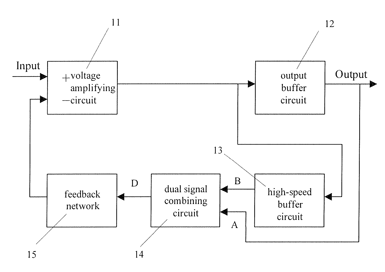
[0028]FIG. 1 shows a block illustrating a circuit of a double sampling negative feedback amplifier in accordance with a first embodiment of the invention. Meaning and usage of each numeral is explained as follows:

[0029]11: voltage amplifying circuit used to output voltage signal and transfer it to a high-speed buffer circuit and an output buffer circuit. In an example embodiment, the voltage amplifying circuit is a differential input voltage amplifying stage.

[0030]12: output buffer circuit used to achieve unit voltage gain, provide amplified output signal and low-frequency feedback sampling signal for a double signal combining circuit.

[0031]13: high-speed buffer circuit used to achieve high speed unit voltage gain and output high-frequency feedback sampling signal to an input of the double signal combining circuit.

[0032]14: double signal combining circuit used to combine the high and low-frequency feedback signals to form one-way compound feedback signal.

[0033]15: feedback netw...

embodiment 2

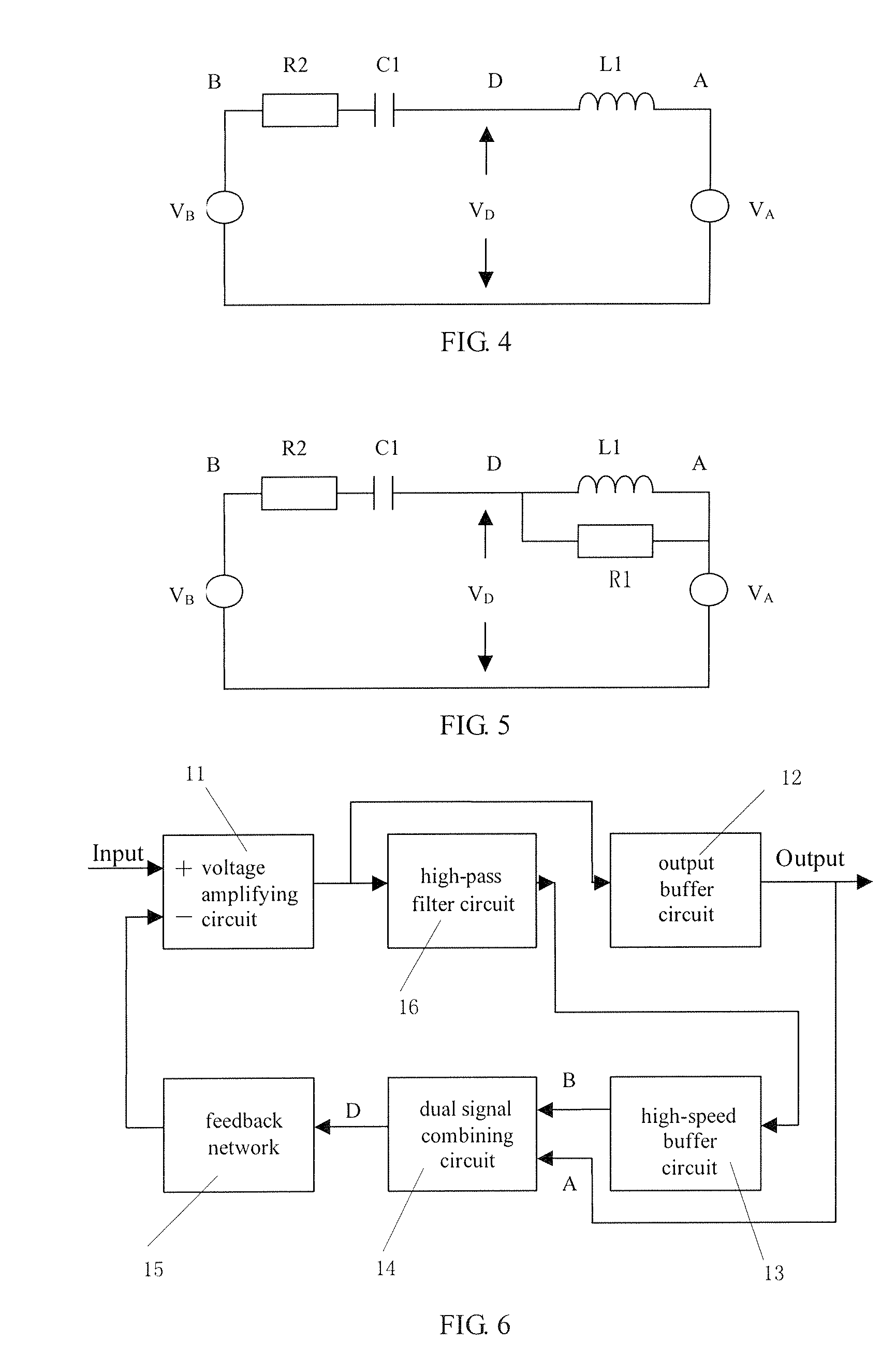
[0047]FIG. 6 shows a block illustrating a circuit of a double sampling negative feedback amplifier in accordance with a second embodiment of the invention. Compared with the first example embodiment, the double feedback amplifying circuit further contains a high-pass filter circuit 16 on the high-frequency sampling channel. The high-pass filter circuit 16 is used to remove the signal of the amplifying signal frequency from the high-frequency sampling channel.

[0048] Because the high-pass filter circuit 16 is incorporated prior to the high-speed buffer circuit 13 to reduce the amplifying signal at node B, the sampling of the amplifying signal in the high-frequency channel is reduced without stability of the feedback circuit being influenced. In the invention, the high-pass filter circuit 16 can be positioned at either the input or output of the high-speed buffer circuit 13.

[0049] After the high-pass filter circuit 16 is incorporated into the high-frequency sampling channel, at the a...

embodiment 3

[0050]FIG. 7 shows a block illustrating a circuit of a double sampling negative feedback amplifier in accordance with a third embodiment of the invention. Compared with the first example embodiment, a voltage gain stage, i.e., an in-phase voltage amplifying circuit 17, is positioned prior to the output buffer circuit 12. The in-phase voltage amplifying circuit 17 enhances the voltage gain at low-frequency channel such that the DC gain at low-frequency channel is higher than that at high-frequency channel, and as a result, the feedback depth of the amplifying frequency is increased. Because the gain at low-frequency channel is higher than that at high-frequency, at the amplifying signal frequency band, the signal voltage level of VB is less than VA and VD. The signal voltage level of VB is less than VA at the crossover frequency. It can be known from the expression of Fs that either the capacitor C1 or the inductor L1 should have a larger value. Thus, we can understand that the circu...


PUM


Abstract

A method for double sampling loop negative feedback comprising: obtaining a low-frequency feedback signal from the output of the amplifier; obtaining a high-frequency feedback signal from part of the amplifier of which high-frequency phase shift is low, wherein two-ways sampling signals have the same amplifying phase; combining the two-ways sampling signals together using a series capacitor-inductor double signal combining circuit to form one signal, the signal having low phase shift at both high and low-frequency and being used for negative loop feedback. The invention also provides a double negative feedback amplifier using the method.

Description

FIELD OF THE INVENTION [0001] The invention relates to an amplifier, and more particularly, to a method for double sampling loop negative feedback and double sampling negative feedback amplifier. BACKGROUND OF THE INVENTION [0002] Loop negative feedback is an important method for improving performance of a linear amplifier. For a loop negative feedback amplifier, larger loop feedback depth results in less distortion of the amplifier. However, further increase in feedback depth is limited by stability of the amplifier. That is to say, if the frequency of amplified signal is higher, the loop negative feedback depth obtainable will be smaller. More particularly, for a power amplifier, since it is necessary to utilize power elements of bad frequency characteristic, or use more stages of buffer amplifiers to provide sufficient gain and to accommodate the complex change of output load, signal of higher-frequency will achieve smaller negative feedback depth. For example, the negative feedb...

Claims


Application Information

Patent Timeline
Patent Type & Authority Applications(United States)
IPC IPC(8): H03F1/34
CPCH03F1/32H03F1/3211H03F1/34H03F3/20H03F3/45094H03F3/3072H03F3/3074H03F3/45085H03F3/3069
Inventor ZHOU, ZONGSHAN
Owner ZHOU ZONGSHAN
Why Eureka
Try Eureka