Passive conductive cooling module

Inactive Publication Date: 2007-12-27
RAYTHEON CO
View PDF12 Cites 26 Cited by
  • Summary
  • Abstract
  • Description
  • Claims
  • Application Information

AI Technical Summary

Benefits of technology

[0004]In accordance with the present invention, a cooling module includes a thermally conductive plate, a bladder disposed on at least one side of the plate, the bladder have a chamber, and fluid disposed in the chamber of the bladder wherein the bladder in an inflated state impresses the cooling module against an adjacent electronic circuit card. With such an arrangement, the cooling module is forcibly pressed against adjacent electronic circuit card providing increased physical stability to the electronic circuit card as well as provide a cooling mechanism for the circuit card.
[0005]In accordance with the present invention, a cooling module adapted to fit between two rack mounted electronic assemblies includes a

Problems solved by technology

COTS (commercial off the shelf) computer processors and circuit cards offer ever-increasing levels of processing power, but require correspondingly larger power

Method used


Image

  • Passive conductive cooling module
  • Passive conductive cooling module
  • Passive conductive cooling module

Examples


Embodiment Construction

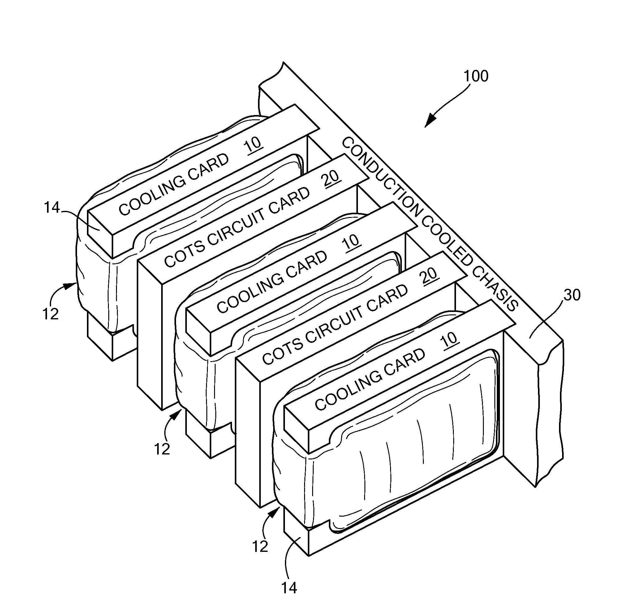
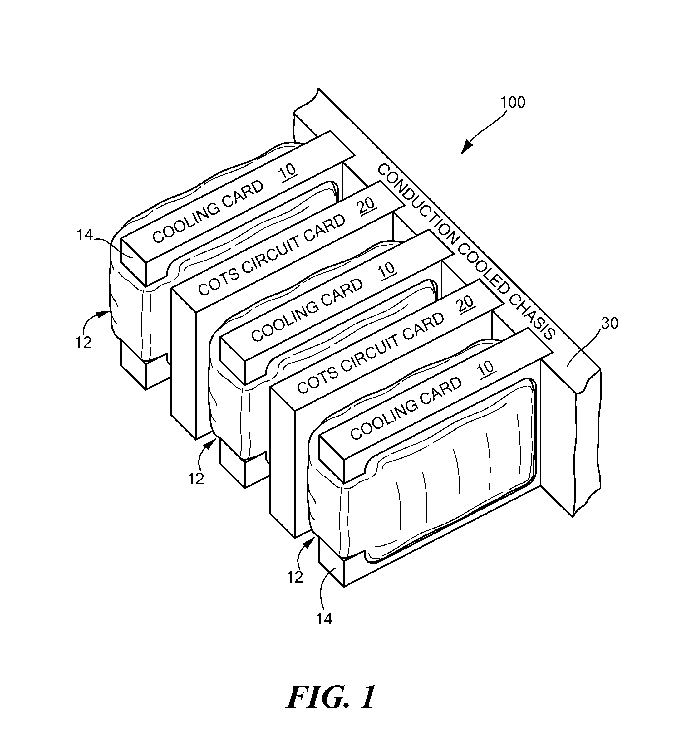
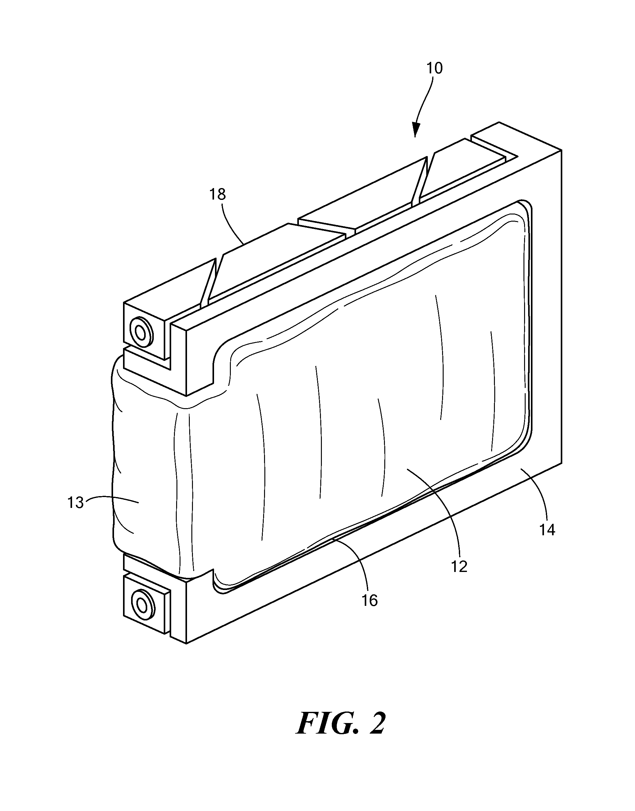
[0013]Referring now to FIG. 1, an electronic assembly 100 is shown to include a cooling module 10 (sometimes also referred to as a cooling card) and a circuit card 20 disposed on a conduction cooled chassis 30. The cooling module 10 includes a flexible bladder 12 filled with thermally conductive fluid (i.e. coolant) and a thermally conductive plate 14. A circuit card 20 is disposed next to a cooling module 10 with the circuit card 20 between two cooling modules 20. This arrangement provides a technique for cooling high-power circuit cards in a conduction-cooled assembly as well as provide additional ruggardization for the circuit cards. It should be noted that this technique allows for adequate cooling of unmodified COTS circuit cards in a ruggedized or thermally challenging environment, i.e. military environment. The cooling card 10 can be a “dummy” card that fits into a single slot in the electronics chassis 30. The cooling module or card 10 has a conduction-cooled plate or frame ...


PUM


Abstract

A cooling module includes a thermally conductive plate, a bladder disposed on at least one side of the plate, the bladder have a chamber, and fluid disposed in the chamber of the bladder wherein the bladder in an inflated state impresses the cooling module against an adjacent electronic circuit card. where the cooling module is forcibly pressed against adjacent electronic circuit card providing increased physical stability to the electronic circuit card as well as provide a cooling technique for the circuit card.

Description

FIELD OF THE INVENTION[0001]This invention relates generally to ruggedized electronic equipment and more particularly to ruggedized electronic assemblies using conduction cooling.BACKGROUND OF THE INVENTION[0002]To prevent electronic equipment from over heating, there are many existing methods to help control thermal management. The simplest is allowing abundant airflow through a card chassis to cool electronic cards directly by convection. In environments where convection is impossible or impractical, individual cards may be built on a thermally conductive frame so that heat is conducted away from the card components to the enclosing chassis. In extreme cases of thermal management, spray cooling may be used to bathe circuit cards directly in a liquid coolant. In some systems, a heat sink or liquid-cooled heat exchanger is attached directly to the body of the electronic component that generates the heat.[0003]Electronics assemblies must overcome the increasing challenge of heat reje...

Claims


Application Information

Patent Timeline
IPC IPC(8): H05K7/20
CPCH05K7/1404H05K7/20636H05K7/20454F28D15/02H05K7/20
Inventor GLAHN, TIMOTHY J.KURTZ, ROBERT G.
Owner RAYTHEON CO
Why Eureka
Try Eureka