Increased tool utilization/reduction in mwbc for UV curing chamber

a technology of uv curing chamber and tool utilization, which is applied in the direction of material analysis using wave/particle radiation, nuclear engineering, railway components, etc., can solve the problems of thermal instability of sacrificial materials, the need to remove the organic fragments of sacrificial materials that are thermally unstable, and the undesirable form of water incorporation

Active Publication Date: 2007-12-27
APPLIED MATERIALS INC
View PDF15 Cites 395 Cited by
  • Summary
  • Abstract
  • Description
  • Claims
  • Application Information

AI Technical Summary

Benefits of technology

[0008]Systems and methods in accordance with embodiments of the present invention can prevent the collection of contaminants, outgassed species, and other materials on components of a processing chamber or other such housing.

Problems solved by technology

Either of these forms of water incorporation is generally undesirable.
Also, in some particular CVD processes, thermally unstable organic fragments of sacrificial materials (resulting from porogens used during CVD to increase porosity) need to be removed.
Conventional thermal anneal steps are generally of relatively long duration (e.g., often between 30 min to 2 hrs.) and thus consume significant processing time and slow down the overall fabrication process.
The use of UV radiation for curing and densifying CVD films can reduce the overall thermal budget of an individual wafer and speed up the fabrication process.
These species tend to collect on various exposed surfaces of the chamber, such as windows in the chamber, that can reduce the efficiency of the process.
Further, the build-up of these species on the surfaces requires periodic cleaning of the chamber surfaces, such as after every 200 wafers processed, which results in significant tool downtime and a corresponding reduction in manufacturing throughput.
In some swept source systems, for example, a MWBC of 800-1200 wafers is considered to be an undesirably low value of MWBC, caused by factors such as the condensation of outgassed materials on relatively cold surfaces of the processing chamber.

Method used


Image

  • Increased tool utilization/reduction in mwbc for UV curing chamber
  • Increased tool utilization/reduction in mwbc for UV curing chamber
  • Increased tool utilization/reduction in mwbc for UV curing chamber

Examples


Embodiment Construction

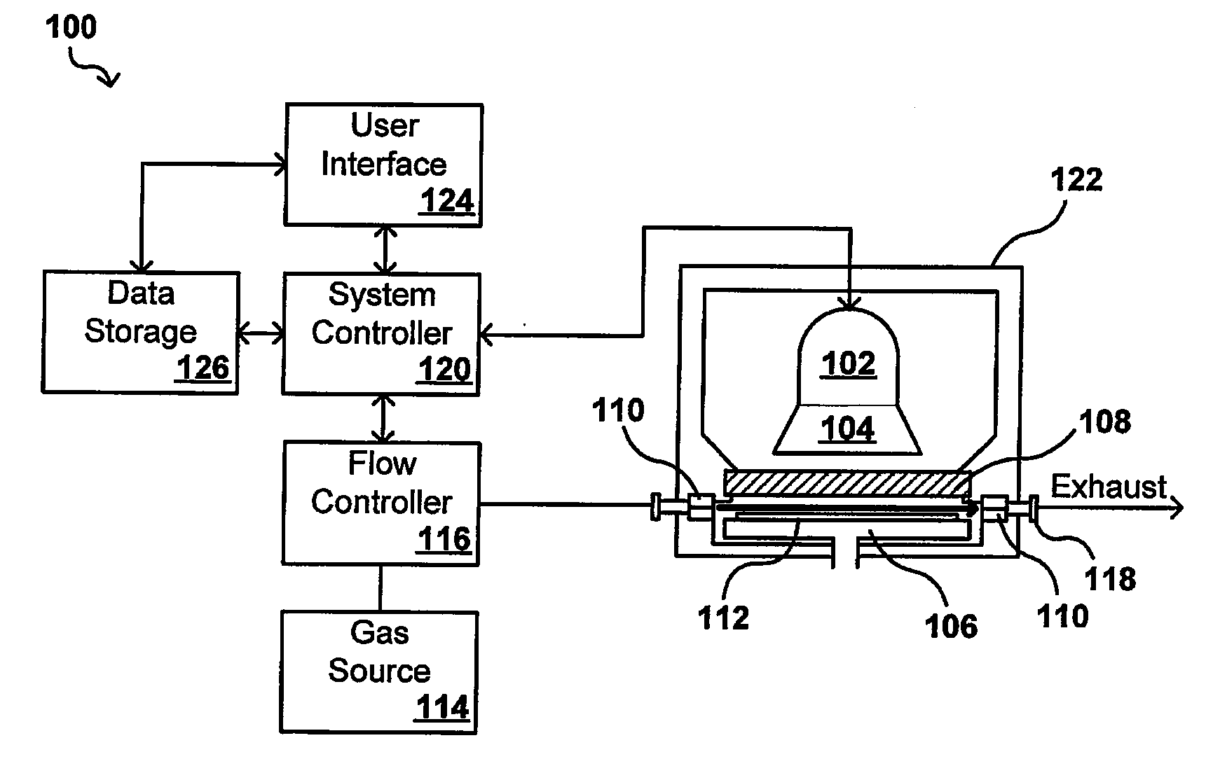
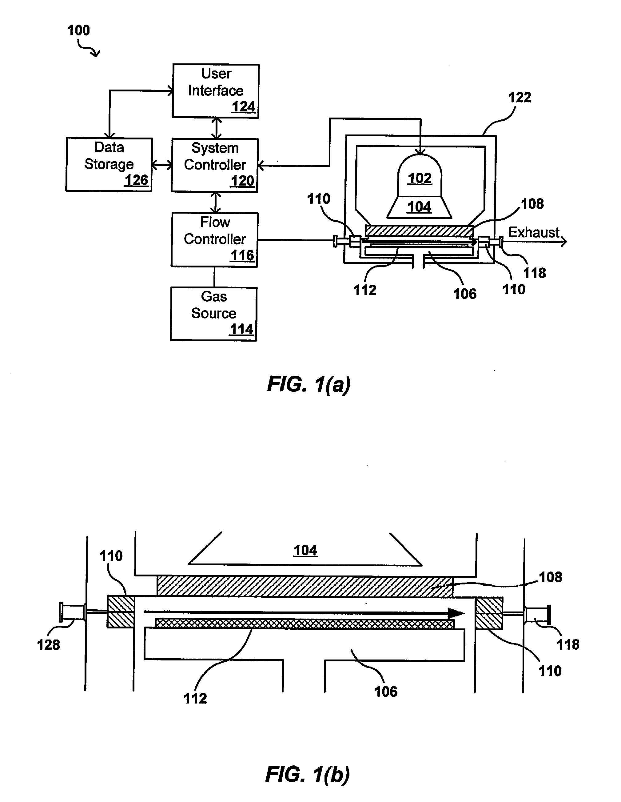
[0021]Systems and methods in accordance with various embodiments of the present invention overcome the aforementioned and other deficiencies in existing anneal, cure, and other processing systems by providing a removal mechanism for outgassed species before those species can collect on the surfaces of the processing chamber. In some embodiments, a pump liner or other component for generating a flow of purge gas can be used in a chamber such as a vacuum chamber to direct a substantially laminar flow of gas across the surface of a wafer or other workpiece during a process such as a UV cure process. Such a flow can carry away any species outgassed by the workpiece. The liner can be passively heated by the convection in the chamber as well as the curing light source, such that the species do not collect on the liner and can be efficiently exhausted from the chamber. In one embodiment, the pump liner is anodized to increase the absorption efficiency of the liner. A window between the wor...


PUM

PropertyMeasurementUnit
anglesaaaaaaaaaa
heightaaaaaaaaaa
widthaaaaaaaaaa

Abstract

A pump liner is used to direct a laminar flow of purge gas across a workpiece to remove contaminants or species outgassed or otherwise produced by the workpiece during processing. The pump liner can take the form of a ring having a plurality of injection ports, such as slits of a variety of shapes and/or sizes, opposite a plurality of receiving ports in order to provide the laminar flow. The flow of purge gas is sufficient to carry a contaminant or outgassed species from the processing chamber in order to prevent the collection of the contaminants on components of the chamber. The pump liner can be heated, via conduction and irradiation from a radiation source, for example, in order to prevent the condensation of species on the liner. The pump liner also can be anodized or otherwise processed in order to increase the emissivity of the liner.

Description

CLAIM OF PRIORITY[0001]This application claims priority to U.S. Provisional Application No. 60 / 816,706, entitled “Increased Tool Utilization / Reduction in MWBC for UV Curing Chamber,” ATTY DOCKET NO. A11051 / T75100, filed Jun. 26, 2006, which is hereby incorporated herein by reference.BACKGROUND OF THE INVENTION[0002]Materials such as silicon oxide (SiOx), silicon carbide (SiC), and carbon doped silicon oxide (SiOCx) films find widespread use in the fabrication of semiconductor devices. One approach for forming such silicon-containing films on a semiconductor substrate is through the process of chemical vapor deposition (CVD) within a chamber. For example, a chemical reaction between a silicon supplying source and an oxygen supplying source may result in deposition of solid phase silicon oxide on top of a semiconductor substrate positioned within a CVD chamber. As another example, silicon carbide and carbon-doped silicon oxide films may be formed from a CVD reaction that includes an o...

Claims


Application Information

Patent Timeline
Patent Type & Authority Applications(United States)
IPC IPC(8): F27D3/00F27D11/00
CPCH01L21/67115F27B17/0025
Inventor ROCHA-ALVAREZ, JUAN CARLOSNOWAK, THOMASBALUJA, SANJEEVKASZUBA, ANDRZEJMUKUTI, NDANKA O.
Owner APPLIED MATERIALS INC
Why Eureka
Try Eureka