Coupling

Inactive Publication Date: 2008-01-03
PARKER HANNIFIN LTD HEMEL HEMPSTEAD
View PDF37 Cites 19 Cited by
  • Summary
  • Abstract
  • Description
  • Claims
  • Application Information

AI Technical Summary

Benefits of technology

[0023] The collar may be arranged to apply a circumferential compressive force to deform the body in any suitable way, for example a so-called shaft clamp, hub clamp or hose type “jubilee” clamp may be used. However, the inner body and the collar preferably each have complimentary camming surfaces inclined to their axes which co-act to apply the circumferential compressive force to deform the body. The collar and the inner body are preferably arranged to be moved relatively towards each other so that the camming surfaces co-act. The collar and the inner body may be moved towards each other by any suitable means, such as by using an appropriate tool

Problems solved by technology

The following problems are associated with these designs: The design relies on the use of controlled material specifications to ensure that the ferrules have enhanced mechanical properties over that of the tube.
This in itself can cause issues as traditional hardening methods such as nitriding induces carbon into the material, which reduces the surfaces corrosion resistance.
Incorrect tube preparation can cause major problems within the assembly of the fitting and this is one aspect that the manufacturer has no control over.
Longit

Method used


Image

  • Coupling
  • Coupling
  • Coupling

Examples


Example

[0043] The following examples discuss the invention being used in conjunction with traditional tube. However the invention can also be used with pipe, solid rod, wire rod or any other round section.

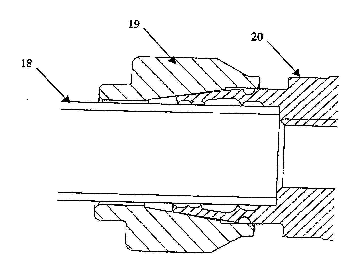
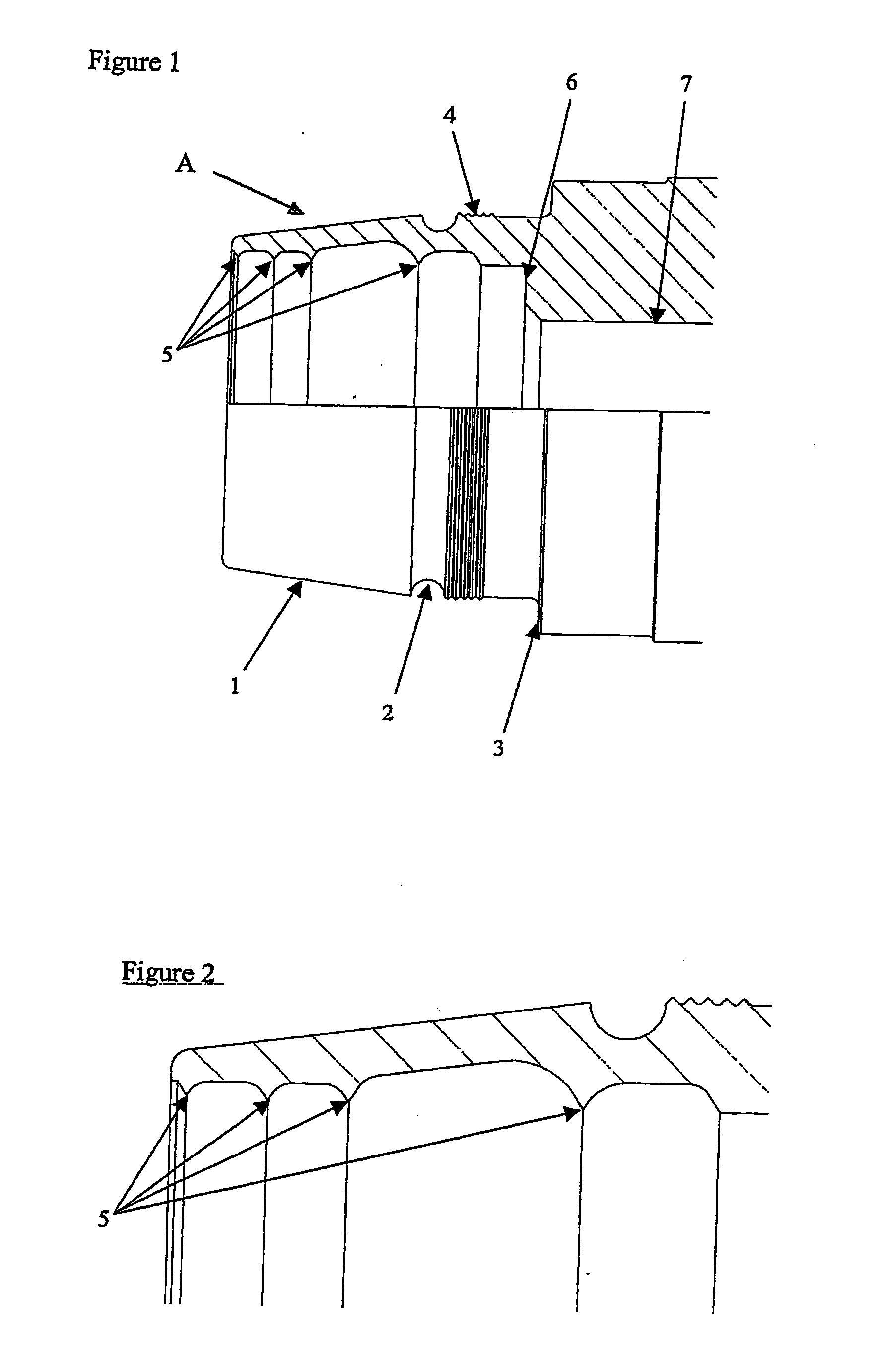
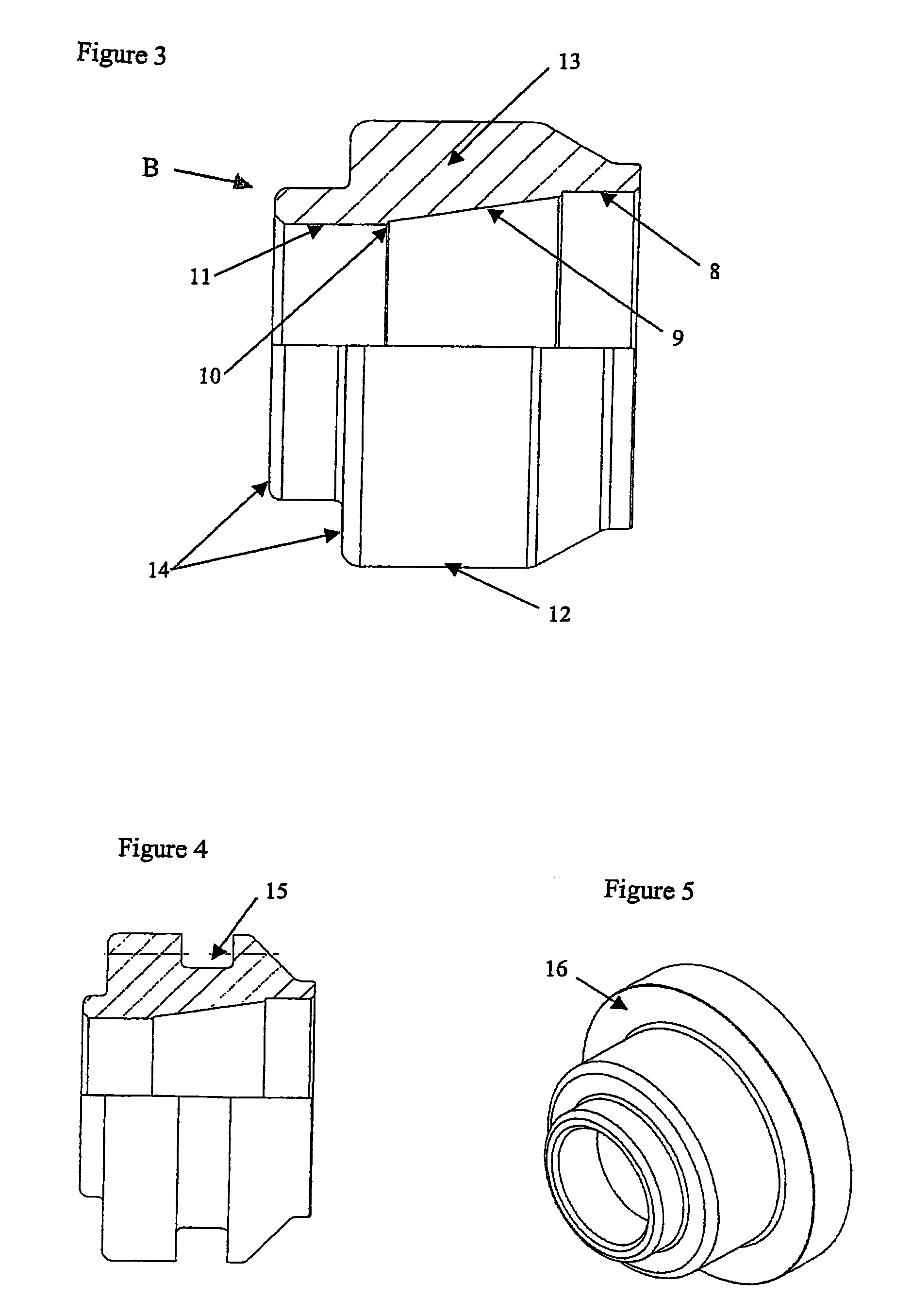
[0044] Embodiments of the invention include a method of attaching a coupling and a coupling that can for example, be machined into a traditional coupling, as will be shown in the following example, or machined onto existing equipment such as, but not limited to, valves, manifolds, pumps, hoses etc. The coupling comprises an inner body or a sealing member as shown for example in FIGS. 1 and 2 and a separate section or collar as shown for example in FIG. 3, which is used to modify the form of the sealing member.

[0045] The sealing member seals against a tube and also retains the tube in position. This member will be referred to as the claw end in the following description and is shown in FIGS. 1 and 2.

[0046] In this example the claw end A has an outside surface with an external frusto-con...


PUM

PropertyMeasurementUnit
Forceaaaaaaaaaa

Abstract

A coupling for attaching to an end of a tube, pipe, conduit or other round solid or hollow section. The coupling includes an inner body and a collar to be provided around the inner body. The inner body has an interior bore passing through at least a portion thereof to receive a tube or the like and the bore has one or more interior annular protuberances extending into the bore. When the collar is provided around the inner body it applies a circumferential compressive force to deform the inner body such that the one or more annular protuberances engage the tube or the like to seal with it.

Description

CROSS REFERENCE TO RELATED APPLICATIONS [0001] This application is continuation of co-pending International Application No. PCT / GB06 / 000035 filed Feb. 17, 2006, which application designated the United States, and which application claims priority to Great Britain Patent Application No. 0502954.0, filed Feb. 25, 2005, and Great Britain Patent Application No. 0515165.9, filed Jul. 22, 2005, the disclosure of each of which applications is incorporated herein by reference.BACKGROUND OF THE INVENTION [0002] The present invention relates to a coupling for attaching tubes, pipes, conduits and other round sections to other such items and / or other systems. [0003] Initially this invention has been developed within the instrumentation tube fittings industry. However, the invention is capable of being utilised within many other applications outside of this environment. Other applications may include shipbuilding, aerospace, automotive, pipe connections, and construction using wire e.g. suspensi...

Claims


Application Information

Patent Timeline
IPC IPC(8): F16L19/06F16L19/08F16L13/14F16L19/10F16L19/14F16L37/138
CPCF16L13/146F16L19/10Y10T29/49927F16L37/138F16L19/14Y10T29/49934F16L13/14F16L21/007F16L21/08
Inventor NICHOLSON, SPENCER
Owner PARKER HANNIFIN LTD HEMEL HEMPSTEAD
Why Eureka
Try Eureka