
Nondestructive inspection method and apparatus for a surface processed by shot peening

a technology of non-destructive inspection and inspection method, which is applied in the direction of heat treatment apparatus, instruments, force/torque/work measurement apparatus, etc., can solve the problems of not being able to measure by destructive method, products manufactured on line, and products that cannot be inspected. , to achieve the effect of short tim

Inactive Publication Date: 2008-01-03
FUJI MFG CO LTD
View PDF3 Cites 26 Cited by
  • Summary
  • Abstract
  • Description
  • Claims
  • Application Information

AI Technical Summary

Benefits of technology

[0017]The present invention is addressed to solve the problems of the above prior art, and provide an inspection method and inspection apparatus that can easily measure a distribution of residual stress of a surface processed by shot peening including a distribution state of residual stress in the depth direction in a relatively short time without destroying the material to be treated.
[0043]The inventive inspection method and inspection apparatus having the inventive structure of the present invention described above can easily measure a state of residual stress of a surface processed by shot peening including a state of residual stress in the depth direction of the material to be treated in a relatively short time without destroying the material to be treated.

Problems solved by technology

The destructive method among these methods measures residual stress by measuring deformation of the material to be treated due to reduction of a layer to be processed (residual stress generation layer) by removal of the surface of the material to be treated through electropolishing or chemical polishing, but the residual stress generated by shot peening, particularly by shot peening using fine particle shots appears only in a very shallow part near the surface of the material to be treated and may not be measured occasionally in the destructive method.
On the other hand, in the nondestructive inspection method using X-ray analysis, residual stress can be measured without destruction of the material to be treated, but an X-ray valid penetration depth is only several μm from the surface, so a state of residual stress can be inspected only at an uppermost surface of the material to be treated, but cannot be inspected in a depth direction.
However, as described above, in shot peening, particularly in shot peening using fine particles, residual stress generates in a relatively shallow part from the surface, so it may not be measured by the destructive method.
However, this inspection of a state of residual stress by X-rays requires destruction of the material to be treated (even if it is a very small or minute opening), so the whole products cannot be inspected and the inspection must be carried out as sampling inspection.
However, there is currently no inspection method and inspection apparatus of this type, thus a sampling inspection must be performed and if a prescribed faulty rate is generated in the sampling inspection, the whole products manufactured on the line is discarded for quality control, for example.
In this method, however, yields are reduced because correctly processed products are also discarded, and incorrectly processed products may be included even if the faulty rate falls within an allowable range.

Method used


Image

  • Nondestructive inspection method and apparatus for a surface processed by shot peening
  • Nondestructive inspection method and apparatus for a surface processed by shot peening
  • Nondestructive inspection method and apparatus for a surface processed by shot peening

Examples


embodiment 1

[0135]As Embodiment 1, the following shows results of inspecting the state of generation of residual stress and the relation of correspondence between Δθ and fP as to SKD61 steel processed by shot peening with fine particles.

[0136]SKD61 steel (hardness: HRC48) is processed by shot peening with fine particles at four different shot injection speeds to create four samples with different states of generation of residual stress.

[0137]FIG. 13 shows results of the relation between the depth from the surface and a distribution of residual stress for each of the prepared samples inspected by X-rays.

[0138]When the states of generation of residual stress are compared under different injecting conditions, the injection speed becomes highest and large residual stress reaches the deepest part in Injecting condition 1.

[0139]The next highest injection speed is achieved in Injecting condition 2, and the next higher speed is achieved in Injecting condition 3. On the other hand, the lowest injection ...

embodiment 2

[0145]As Embodiment 2, the following shows results of actual measurement of the state of generation of residual stress and the relation of correspondence between Δθ and fP when carburized and quenched SCr420 steel processed by shot peening with fine particles is used as a sample.

[0146]FIG. 19 shows results of measurement of a distribution in depth of retained austenite before and after the SCr420 steel is processed by shot peening with fine particles. The carburized and quenched. SCr420 steel includes retained austenite, after being processed by shot peening with fine particles, the retained austenite transforms into martensite, thereby, a content of the retained austenite is decreased.

[0147]FIG. 20 is an f-Δθ diagram obtained by applying the method of the present invention before X-ray measurements. Since the magnetic permeability is increased when retained austenite transforms into martensite, it can be recognized that the f-Δθ diagram has the local maximum value, thereby, the pre...


PUM


Abstract

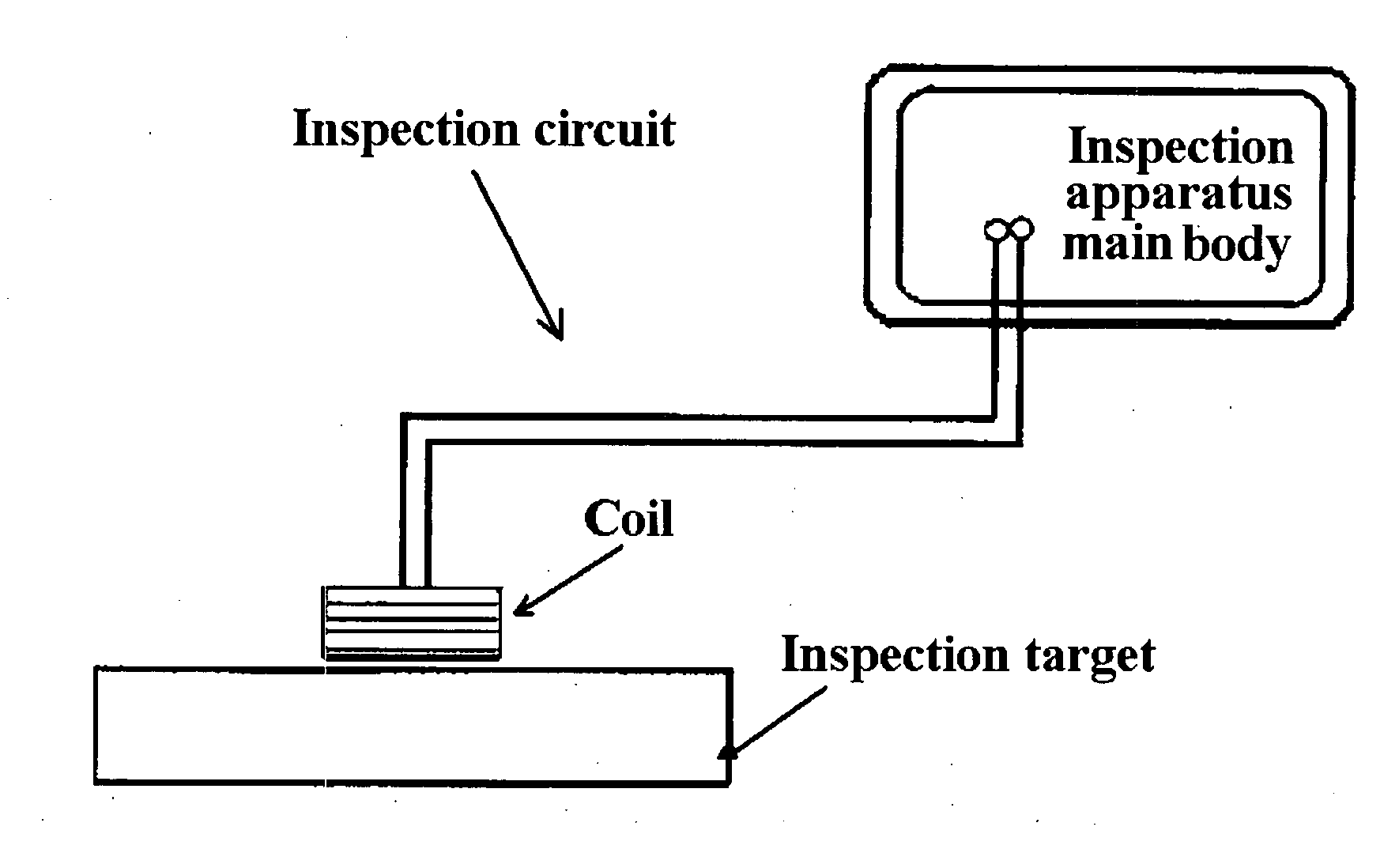
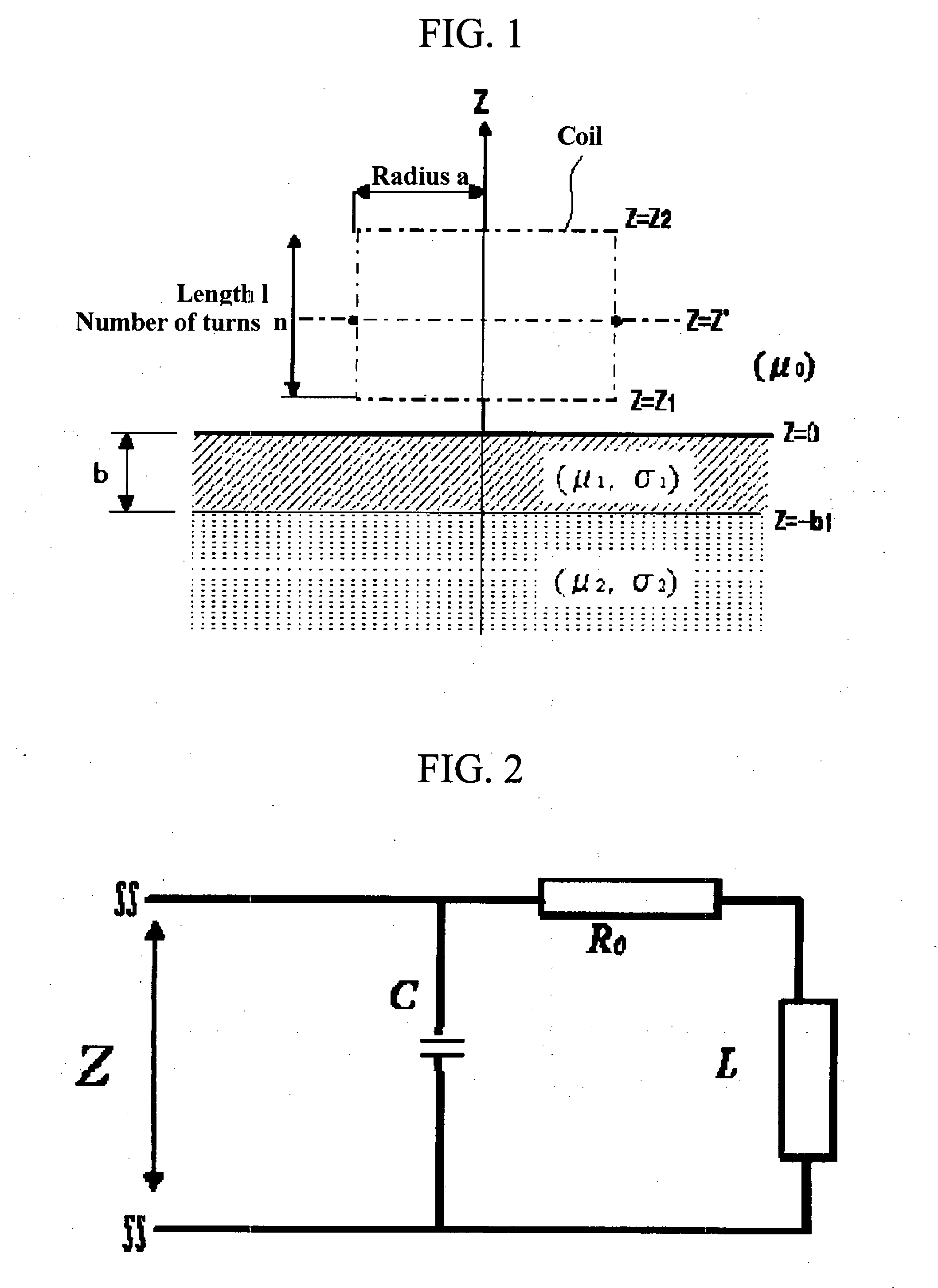
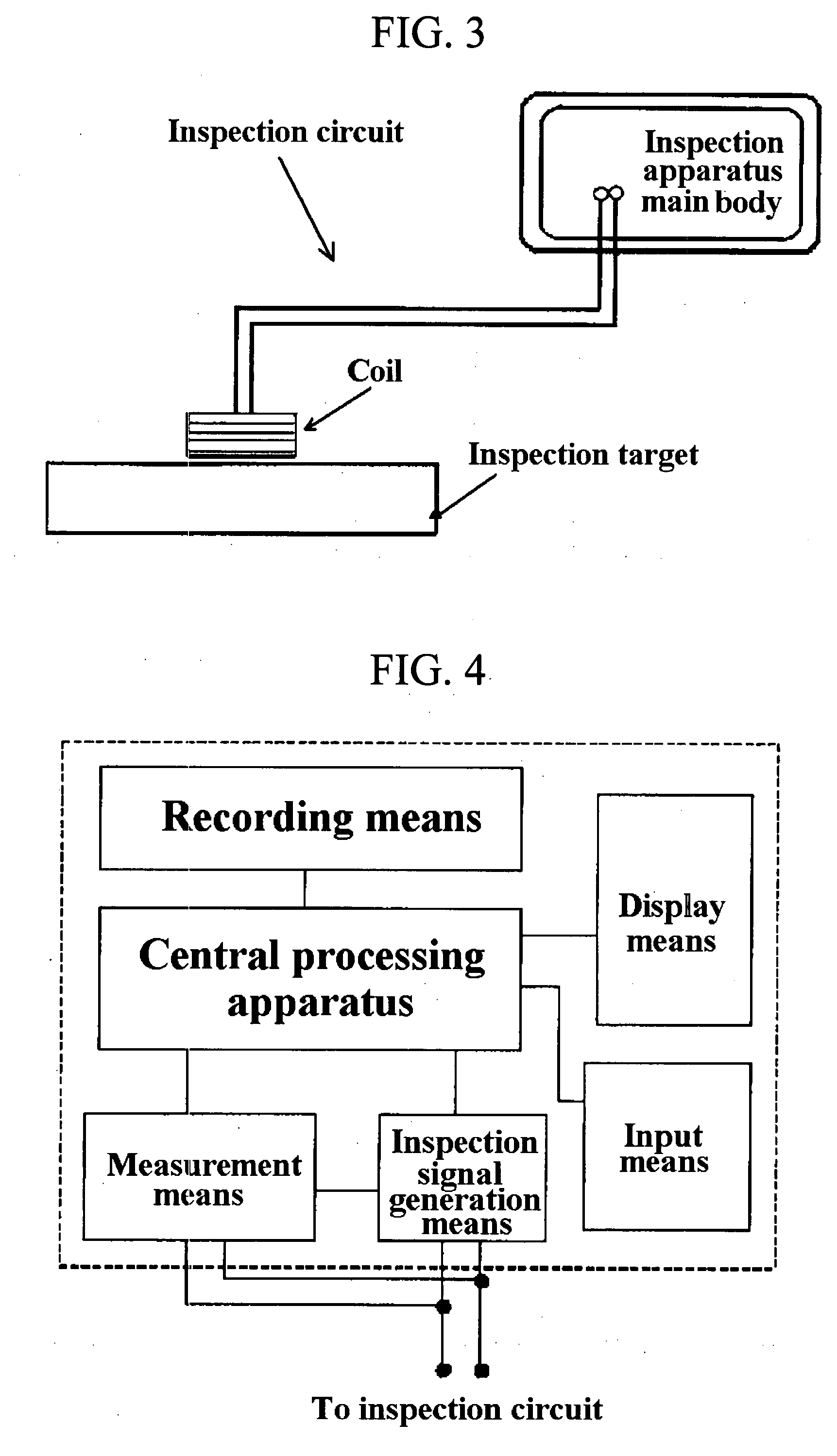
To provide an inspection method and an inspection apparatus that can easily measure a distribution of residual stress on a surface processed by shot peening, including a state of distribution in a depth direction of a material to be treated in a relatively short time without destroying the material to be treated.A coil provided in the inspection circuit is arranged on a surface processed by shot peening of the inspection target, an alternating current signal is input to the inspection circuit with changing a frequency so that frequency response characteristics of impedance of the inspection circuit is measured and acquired as inspection target data, and the inspection target data is compared to frequency response characteristics of impedance acquired from a sample of which a state of generation of residual stress is found.

Description

BACKGROUND OF THE INVENTION[0001]1. Field of the Invention[0002]The present invention relates to a nondestructive inspection method and nondestructive inspection apparatus for inspecting the generation status of residual stress nondestructively in a steel material on which a treatment of shot peening was processed, more particularly relates to a nondestructive inspection method and nondestructive inspection apparatus appropriate for the inspection of surfaces processed by shot peening with fine particle shots with a diameter of tens of[0003]2. Description of the Prior Art[0004]When a surface treatment of a steel material to be treated is performed by shot peening, plastic deformation of the surface of the material to be treated is implemented by a collision of shots and the result thereof; residual stress is generated.[0005]This residual stress is a factor determining strength of the material to be treated, particularly bending strength, torsion strength, bending fatigue strength, t...

Claims


Application Information

Patent Timeline
IPC IPC(8): G01R27/04G01R27/32
CPCB24C9/00G01N27/9046C21D11/00G01L1/00G01N27/02
Inventor KOJIMA, TAKASHIKUMAGAI, MASAOHOSHIKAWA, KIYOSHIISHIBASHI, SHOZO
Owner FUJI MFG CO LTD
Learn More