Phosphor, method for manufacturing same, and light emitting diode

Active Publication Date: 2008-01-03
SEOUL SEMICONDUCTOR
View PDF6 Cites 31 Cited by
  • Summary
  • Abstract
  • Description
  • Claims
  • Application Information

AI Technical Summary

Benefits of technology

[0014]The present invention is conceived to solve the problems of the conventional techniques as described above, and an object of the present invention is to provide a p

Problems solved by technology

Additionally, the oxide-based phosphors such as YAG:Ce and (Ba, Sr, Ca)2SiO4:Eu are likely to be affected by an increase in temperature of the light emitting diode chip and thus undergo a rapid deterioration of fluorescent characteristics.
It is believed that the deterioration of the fluorescent characteristics caused by the temperature increase is affected by the bonding strength of compounds and a size difference between the activators and the host lattice.
However, such a white light emitting diode exhibits low color rendering due to lack of a spectrum in green and red regions relating to the phosphors emitting single yellow light, and, in particular, the white light emitting diode is difficult to realize natural or similar colors due to a

Method used


Image

  • Phosphor, method for manufacturing same, and light emitting diode
  • Phosphor, method for manufacturing same, and light emitting diode
  • Phosphor, method for manufacturing same, and light emitting diode

Examples


embodiment 1

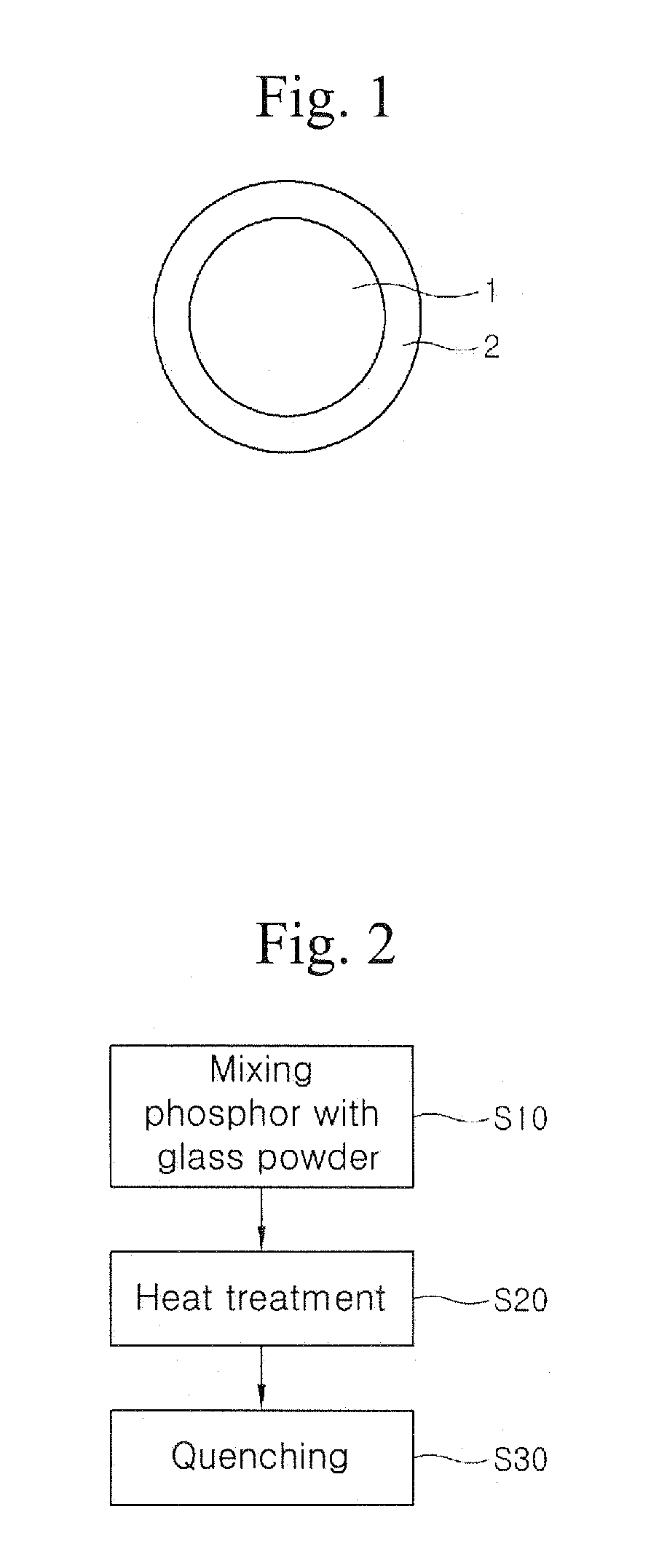
[0043]In this embodiment, a phosphor grain 1 comprises various kinds of phosphor. For example, the phosphor grain 1 may comprises an oxide-based phosphor such as YAG:Ce, (Ba, Sr, Ca)2SiO4:EU, etc., or a sulfide-based phosphor such as (Ca, Sr)S:Eu, SrGa2S4:Eu, ZnS:Cu, Al or (Zn, Cd)S:Ag or Cl, etc.

[0044]The glass coating layer 2 has a composition expressed by the following Formula 1:

a(M′2)O-b(M″O)-c(M′″2O3)-d(M″″O2)-e(M′″″2O5)

Here, M′ is one element selected from the group consisting of Li, Na and K, M″ is at least one element selected from the group consisting of Mg, Ca, Sr, Ba, Cu, Zn, Pb and Be, M′″ is at least one element selected from the group consisting of B, Al, Ga, In, Fe, Y, La, Sc and Bi, M″″ is at least one element selected from the group consisting of Si, Ti and Ge, and M′″″ is at least one element selected from the group consisting of P, Ta and V. Further, a, b, c, d and e are set in the ranges of 0≦a≦0.6, 0≦b≦0.6, 0≦c≦0.6, 0≦d≦0.95, and 0≦e ≦0.2.

[0045]It should be note...

embodiment 2

[0059]In this embodiment, a phosphor grain 1 may comprise, for example, a sulfide-based phosphor that is likely to react with moisture irrespective of its excellent fluorescent characteristics, i.e., sulfide-based phosphors such as (Ca, Sr)S:Eu, (Ca, Sr, Ba)(Al, Ga, In)2S4:Eu, etc.

[0060]A glass coating layer 2 comprises a composite oxide of SiO2, AlO2 / 3(or AlO2 / 3) or SiO2-AlO2 / 3. In particular, when the glass coating layer 2 is comprised of the composite oxide of SiO2-AlO2 / 3, the phosphor exhibits further excellent moisture stability. Here, it is apparent to those skilled in the art that the composite oxide of SiO2-AlO2 / 3 satisfies Formula 1 of the first embodiment described above.

[0061]The phosphor comprises the glass coating layer 2 in an amount of about 0.1˜15 wt % to a phosphor grain. Further, for the glass coating layer 2 comprised of the composite oxide of SiO2-AlO2 / 3, a mixing ratio of SiO2 to AlO2 / 3 is preferably in the range of about 95:5 to about 30:70 by weight, and more ...

embodiment 3

ght Emitting Diode

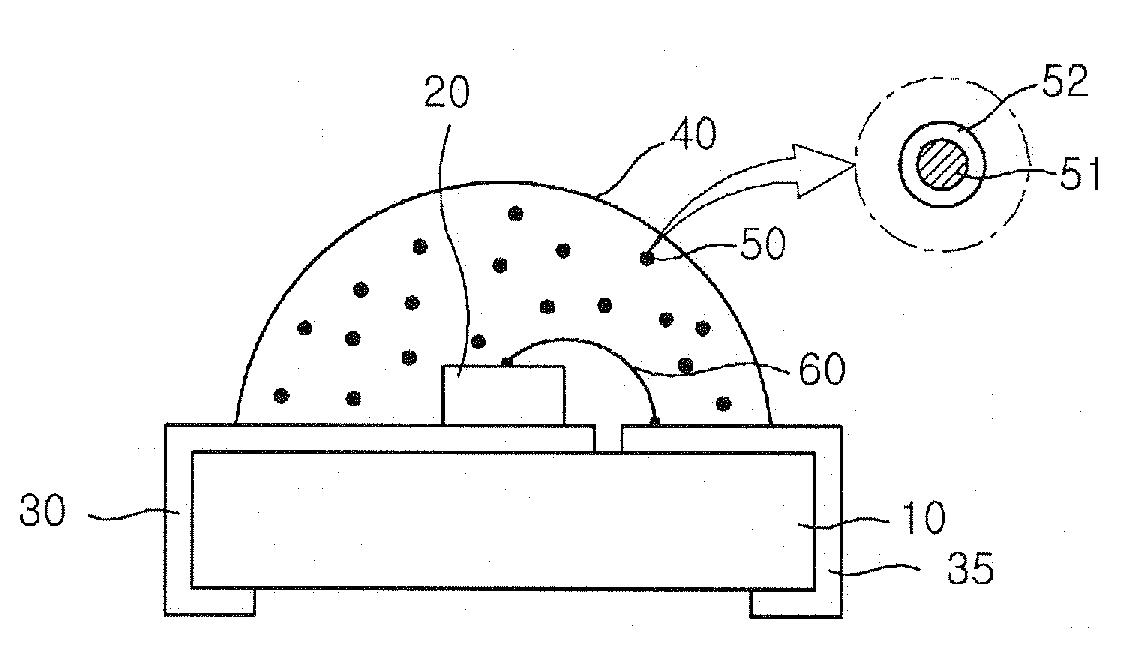
[0092]FIG. 11 is a cross-sectional view of a chip-type light emitting diode manufactured using a phosphor according to the invention. Referring to FIG. 11, the light emitting diode comprises a substrate 10, first and second electrodes 30 and 35 formed on the substrate 10, a light emitting diode chip 20 mounted on the first electrode 30, and a molding part 40 to envelope the light emitting diode chip 20. Phosphors 50, each of which has a coating layer 52 formed on the surface of a phosphor grain 51 as described above, are uniformly distributed in the molding part 40.

[0093]A recess having an inclined sidewall is formed on a central region of the substrate 10 where the light emitting diode chip 20 will be mounted. Here, with the light emitting diode chip 20 mounted on the bottom of the recess, the inclined sidewall of the recess enables maximization of reflection of light emitted from the light emitting diode chip 20, improving light emitting efficiency thereof Furthe...


PUM

PropertyMeasurementUnit
Temperatureaaaaaaaaaa

Abstract

A phosphor is formed with a glass coating layer on a surface of a phosphor grain to have improved moisture and/or thermal stability. A method for manufacturing the phosphor comprises preparing phosphor grains excitable by light, and forming a glass coating layer on a surface of each phosphor grain. The glass coating layer may be formed by mixing the phosphor grains with a glass composition; heat-treating a mixture of the phosphor grains and the glass composition to make the glass composition melt and surround the phosphor grains; and cooling and breaking the heat-treated mixture to provide phosphors, each comprising the phosphor grain having the glass coating layer formed on a surface of the phosphor grain.

Description

CROSS-REFERENCE TO RELATED APPLICATION[0001]This application claims priority of Korean Patent Applications Nos. 10-2006-0058831, filed Jun. 28, 2006, and 10-2006-0060972, filed Jun. 30, 2006, the contents of which are incorporated herein by reference in their entirety.BACKGROUND OF THE INVENTION[0002]1. Field of the Invention[0003]The present invention relates to a phosphor, a method for manufacturing the same, and a light emitting diode. More particularly, the present invention relates to a phosphor having moisture and / or heat stability, a method for manufacturing the same, and a light emitting diode using the phosphor.[0004]2. Description of the Related Art[0005]Phosphors known in the art include oxide-based phosphors, sulfide-based phosphors, recently developed nitride-based phosphors, and the like. The phosphors are typically excited by light from a blue or UV light emitting diode chip, and require moisture or heat stability to maintain good light emitting characteristics of a l...

Claims


Application Information

Patent Timeline
IPC IPC(8): C01B15/16C01B25/00H01L33/32H01L33/50H01L33/56H01L33/62
CPCC03C1/008C03C17/007C09K11/025C09K11/0883C09K11/642C09K11/7731C09K11/7734H01L2224/48247C09K11/7774C09K11/883H01L33/502H01L2224/48091H01L2924/00014H01L2924/181C09K11/77342H01L2924/00012
Inventor KIM, KYUNG NAMMATSUOKA, TOMIZOCHANG, MI YOUN
Owner SEOUL SEMICONDUCTOR
Why Eureka
Try Eureka