System and method for providing Jones matrix-based analysis to determine non-depolarizing polarization parameters using polarization-sensitive optical coherence tomography

Inactive Publication Date: 2008-01-10
THE GENERAL HOSPITAL CORP
View PDF101 Cites 192 Cited by
  • Summary
  • Abstract
  • Description
  • Claims
  • Application Information

AI Technical Summary

Benefits of technology

[0031] Pursuant to a further exemplary embodiment of the present invention, at least one ophthalmic imaging sixth arrangement can be provided which is configured to received the third electromagnetic radiation, and produce the fifth electromagnetic radiation. A processing arrangement can be provided, which when executing a predetermined technique, can be configured to receive data associated with the amplitude and/or the phase of

Problems solved by technology

However, an optical fiber has a disadvantage of that propagation through optical fiber can alter the polarization state of light.
In this case, the polarization state of light incident on the sample is not easily controlled or determined.
However, all of these techniques are disadvantageous in some manner.
These techniques typically invoke a

Method used


Image

  • System and method for providing Jones matrix-based analysis to determine non-depolarizing polarization parameters using polarization-sensitive optical coherence tomography
  • System and method for providing Jones matrix-based analysis to determine non-depolarizing polarization parameters using polarization-sensitive optical coherence tomography
  • System and method for providing Jones matrix-based analysis to determine non-depolarizing polarization parameters using polarization-sensitive optical coherence tomography

Examples


Embodiment Construction

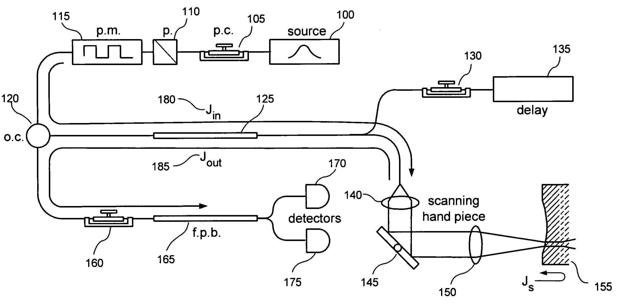
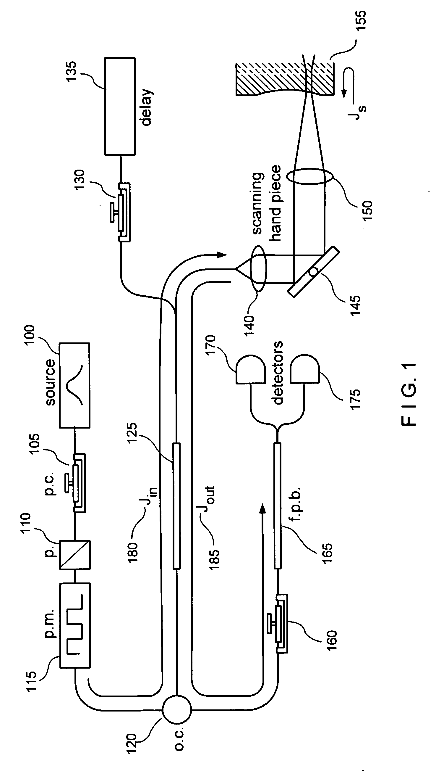
[0039] The exemplary embodiments of systems, software arrangements and processes can be implemented in a variety of OCT or OFDI systems. FIG. 1 shows an exemplary embodiment of a fiber-based polarization-sensitive time-domain OCT arrangement which is and / or that can be used for implementing the exemplary embodiments of the system, process, and software arrangement according to the present invention.

[0040] The exemplary embodiments of the method, system and arrangement according to the present invention can be implemented in a variety of imaging systems. For example, as shown in FIG. 1, the exemplary arrangement which is and / or may be used with exemplary embodiments of the present invention is provided with components of an exemplary fiber-based OCT system, and a standard single-mode fiber may be used throughout such arrangement. In particular, the arrangement includes a light (e.g., broadband) source 100 which is adapted to generate an electromagnetic radiation or light signal. A p...


PUM


Abstract

Arrangement, system and method for a polarization effect for a interferometric signal received from sample in an optical coherence tomography (“OCT”) system are provided. In particular, an interferometric information associated with the sample and a reference can be received. The interferometric information is then processed thereby reducing a polarization effect created by a detection section of the OCT system on the interferometric signal. Then, an amount of a diattenuation of the sample is determined. The interferometric information can be provided at least partially along at least one optical fiber which is provided in optical communication with and upstream from a polarization separating arrangement. In another exemplary embodiment of the present invention, apparatus and method are provided for transmitting electromagnetic radiation to the sample. For example, at least one first arrangement can be provided which is configured to provide at least one first electromagnetic radiation. A frequency of radiation provided by the first arrangement can vary over time. At least one polarization modulating second arrangement can be provided which is configured to control a polarization state of at least one first electromagnetic radiation so as to produce at least one second electromagnetic radiation. Further, at least one third arrangement can be provided which is configured to receive the second electro-magnetic radiation, and provide at least one third electromagnetic radiation to the sample and at least one fourth electromagnetic radiation to a reference. The third and fourth electromagnetic radiations may be associated with the second electromagnetic radiation.

Description

CROSS-REFERENCE TO RELATED APPLICATION(S) [0001] This application is based upon and claims the benefit of priority from U.S. Patent Application Ser. No. 60 / 623,773, filed Oct. 29, 2004, the entire disclosure of which is incorporated herein by reference.STATEMENT OF FEDERAL SUPPORT [0002] This invention was made, at least in part, with Government support under grant numbers R01EY014975, and R01RR19768 from the National Institute of Health, and grant numbers F49620-01-10014 and FA-9550-04-1-0079 from the Department of Defense. The Government may have certain rights to the invention described and claimed herein.FIELD OF THE INVENTION [0003] The present invention relates to systems and methods for a fiber-based optical imaging using a low coherence light beam reflected from a sample surface and combined with reference light beam, in which an evolution of the polarization state of the sample arm light can be used to determine the polarization parameters of the sample. BACKGROUND OF THE I...

Claims


Application Information

Patent Timeline
IPC IPC(8): G01B9/02G01B11/02
CPCA61B5/0066A61B5/0073G01N21/4795A61B5/4523A61B5/4519
Inventor PARK, BORIS HYLEDE BOER, JOHANNES F.
Owner THE GENERAL HOSPITAL CORP
Why Eureka
Try Eureka