Recursive phase estimation for a phase-shift-keying receiver

Inactive Publication Date: 2008-01-10
ALCATEL-LUCENT USA INC
View PDF29 Cites 17 Cited by
  • Summary
  • Abstract
  • Description
  • Claims
  • Application Information

AI Technical Summary

Benefits of technology

[0010]In one embodiment, a receiver of the invention has a detector coupled to a digital processor. The detector is adapted to mix the received PSK signal with an LO signal having a time-varying phase offset with respect to the carrier frequency of the PSK signal to produce a digital measure of the PSK signal. The digital processor is adapted to: (i) estimate a frequency offset between the carrier frequency of the PSK signal and the LO signal; (ii) remove from an angular component of the digital measure a component corresponding to the frequency offset to generate a frequency-offset-adjusted signal; (iii) for each time slot of the PSK signal, estimate the phase of a respective PSK constellation symbol based on an angular component of the frequency-offset-adjusted signal and an angular component of a recursive function; (iv) estimate a phase differential for a PSK-symbol transition based on two consecutive phase estimates; (v) map each estimated phase differential onto a increment corresponding to a symbol transition in the PSK constellation; and (vi) recover a data seq

Problems solved by technology

Unfortunately, suitable coherent optical receivers are typically relatively difficult to design and/or relatively expensive to build.
If that laser source is used in a coherent optical receiver as an LO source, then its relatively large linewidth might produce a phase uncertainty/noise that can make the op

Method used


Image

  • Recursive phase estimation for a phase-shift-keying receiver
  • Recursive phase estimation for a phase-shift-keying receiver
  • Recursive phase estimation for a phase-shift-keying receiver

Examples


Embodiment Construction

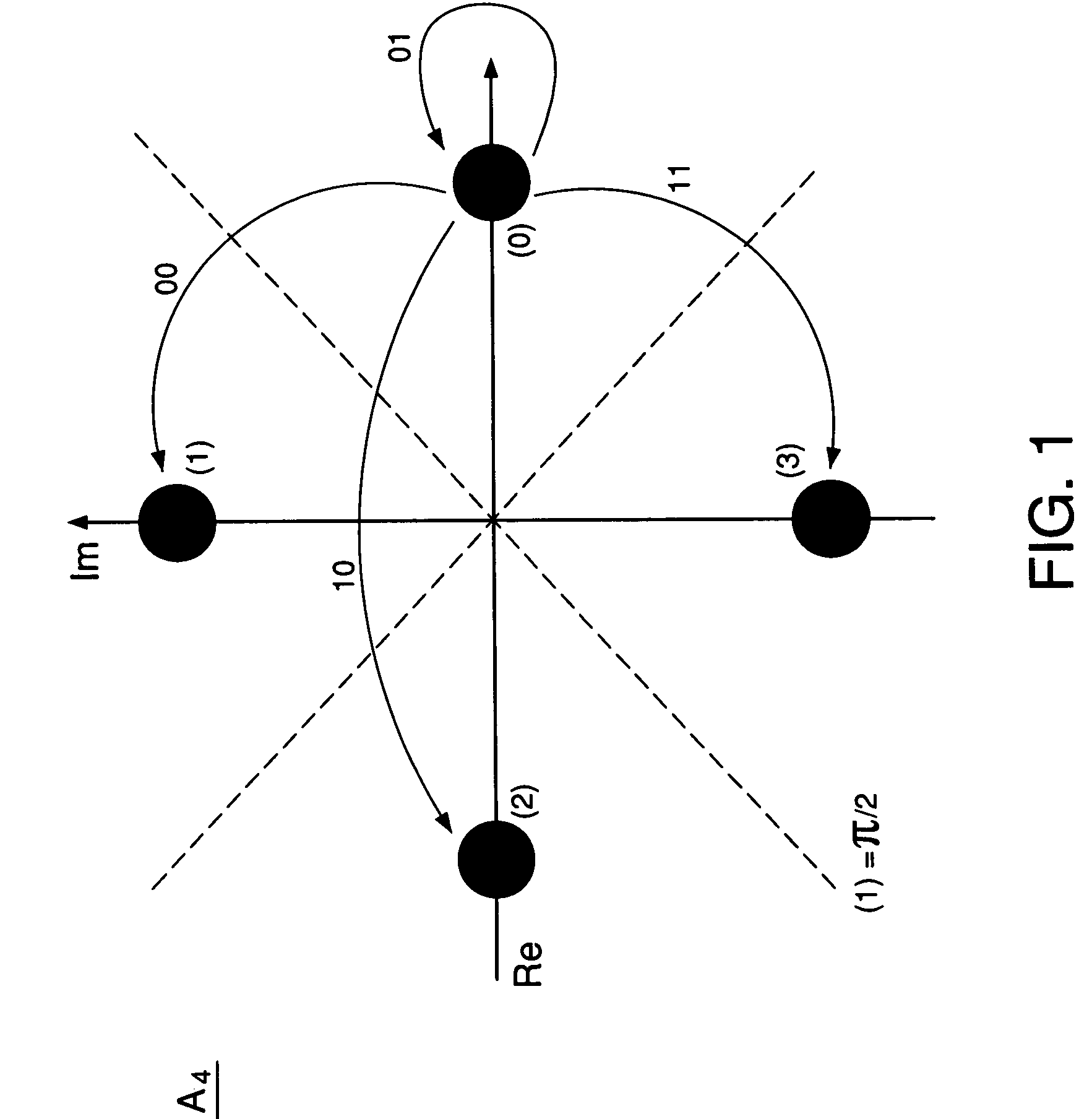
[0020]FIG. 1 graphically shows a representative quadrature-phase-shift-keying (QPSK) constellation that can be used in various embodiments of the invention. Symbol set A4 of the QPSK constellation has four symbols labeled (0) through (3) that are described by Eq. (1):

A4=±1,±j   (1)

where symbols (0) and (2) lie on the real (Re) axis of the complex plane, and symbols (1) and (3) lie on the imaginary (Im) axis of the complex plane. Using the constellation of FIG. 1, data are encoded in a differential manner by assigning a particular two-bit value to each transition between the constellation symbols. The arrows in FIG. 1 illustratively show four possible transitions that involve symbol (0) as a start state, with the assigned binary values indicated next to the respective arrows. For example, the (0)→(1) transition is assigned a binary value of 00. Similarly, the (0)→(2) and (0)→(3) transitions are assigned binary values of 10 and 11, respectively. Finally, the (0)→(0) transition is assi...


PUM


Abstract

In one embodiment, a receiver of the invention has a detector coupled to a digital processor. The detector is adapted to mix the received PSK signal with a local oscillator (LO) signal having a time-varying phase offset with respect to the carrier frequency of the PSK signal to produce a digital measure of the PSK signal. The digital processor is adapted to: (i) estimate a frequency offset between the carrier frequency of the PSK signal and the LO signal; (ii) remove from an angular component of the digital measure a component corresponding to the frequency offset to generate a frequency-offset-adjusted signal; (iii) for each time slot of the PSK signal, estimate the phase of a respective PSK constellation symbol based on an angular component of the frequency-offset-adjusted signal and an angular component of a recursive function; (iv) estimate a phase differential for a PSK-symbol transition based on two consecutive phase estimates; (v) map each estimated phase differential onto a phase increment corresponding to a symbol transition in the PSK constellation; and (vi) recover a data sequence encoded in the PSK signal based on the mapping results.

Description

BACKGROUND OF THE INVENTION[0001]1. Field of the Invention[0002]The present invention relates to communication equipment and, more specifically, to equipment for coherent detection of phase-shift-keying (PSK) signals.[0003]2. Description of the Related Art[0004]Delivery of multimedia services (e.g., telephony, digital video, and data) that is implemented using optical phase-shift keying (PSK) signals has certain advantages, e.g., over that implemented using conventional electrical analog or digital signals. More specifically, some of the advantages are: the ability to carry various / multiple multimedia services over the same optical communication channel; the ability to maintain a selected bit-error rate (BER) with relatively low carrier-to-noise ratios; relatively high tolerance to nonlinear signal distortions; and relatively high spectral efficiency and transmission capacity. As a result, cable companies are upgrading their hybrid fiber coaxial (HFC) networks to improve / create a fu...

Claims


Application Information

Patent Timeline
IPC IPC(8): H04L27/22
CPCH04L27/0014H04L27/2335H04L27/2275
Inventor KOC, UT-VA
Owner ALCATEL-LUCENT USA INC
Why Eureka
Try Eureka