[0020]However, the primary use of the methods and devices described herein is in the assessment of the size, shape, topography, compliance, spatial orientation, and other physical properties of the native heart valves. Such assessments are useful to facilitate proper
sizing, selection, and implantation of
prosthetic heart valves into the
native valve space. Proper selection and
sizing ensures that the
prosthetic heart valve that is delivered during the
implantation procedure will be of a size and shape that fits within the
native valve space, including accommodations for any defects or deformities that are detected by the assessment process. Proper selection and
sizing also ensures that the
prosthetic valve, once fully expanded, will properly seal against the
aortic wall to prevent leakage, and to prevent migration of the
prosthetic valve.
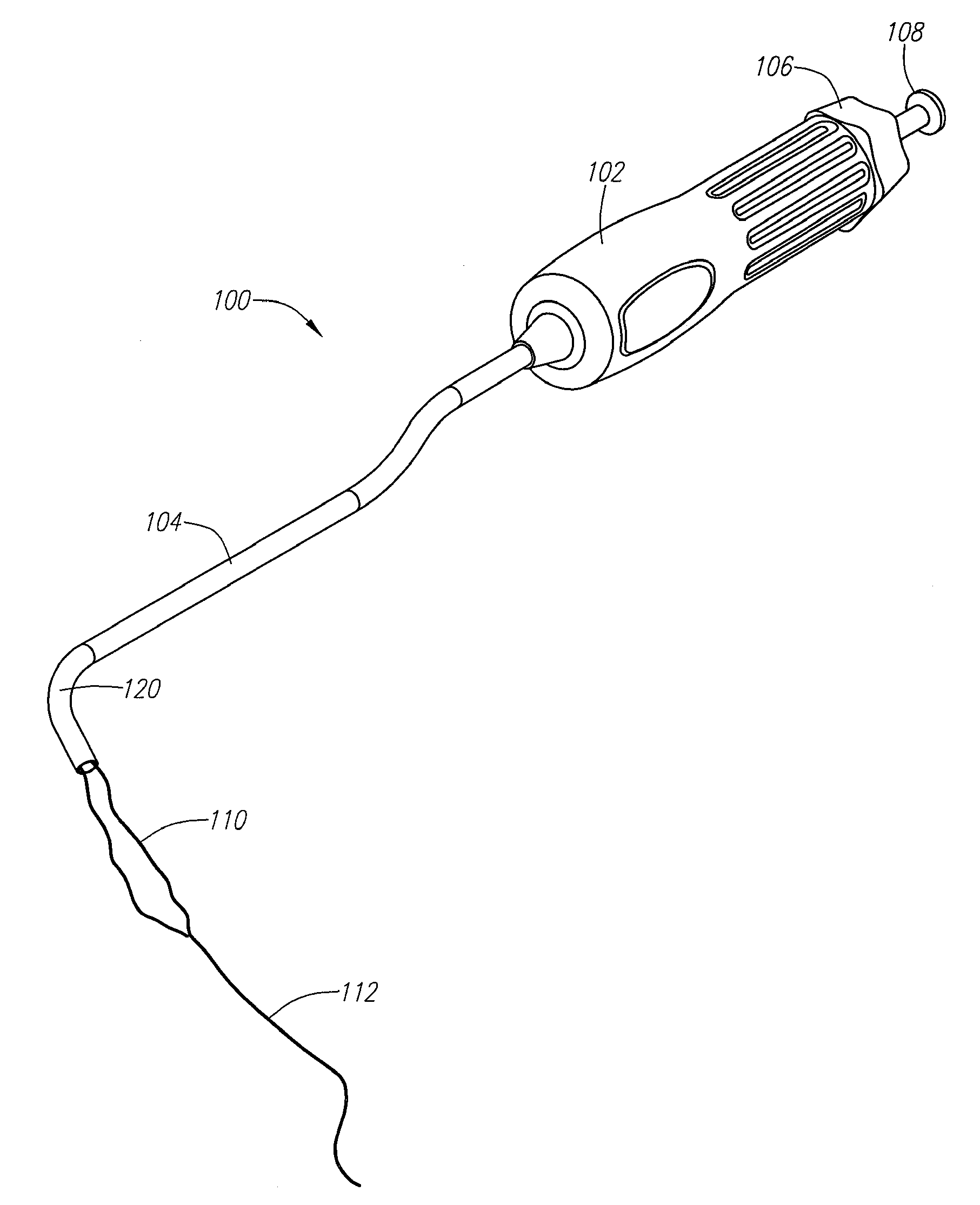
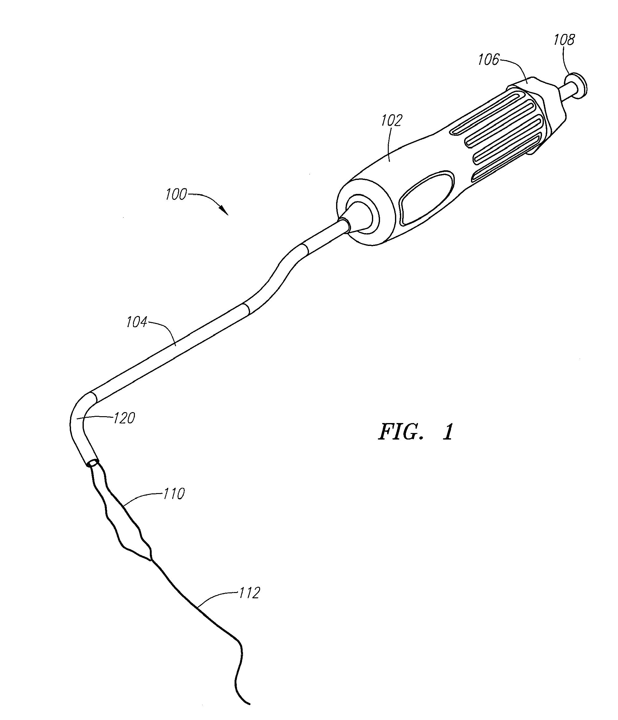
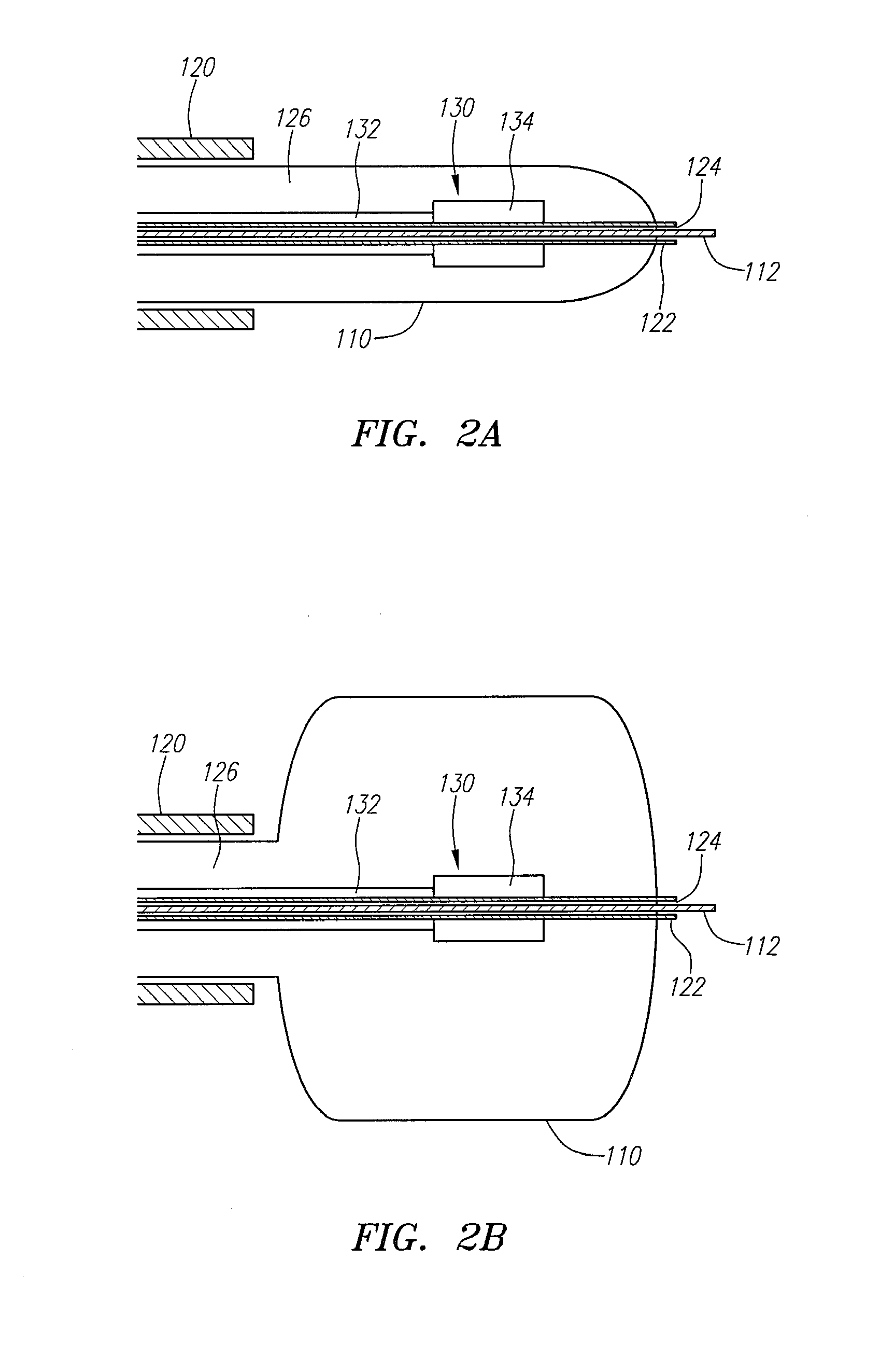
[0026]In the preferred embodiments, the expandable structure is a balloon member. The balloon member is connected to an inflation lumen that runs between the proximal and distal ends of the
catheter, and that is selectively attached to a source of inflation medium at or near the proximal end of the catheter. The balloon member is thereby selectively expandable while the imaging device is located either partially or entirely within the interior of the balloon. The imaging device is adapted to be advanced, retracted, and rotated within the balloon, thereby providing for imaging in a plurality of planes and providing the ability to produce three-dimensional images of the treatment site.
[0027]In optional embodiments, the expandable structure is filled with a medium that enhances the imaging process. For example, the medium may comprise a material that increases the transmission capabilities of the ultrasonic
waves or other imaging energy, or that reduces the amount of scattering of the imaging energy that would otherwise occur without use of the imaging-enhancing medium. In still other optional embodiments, the expandable structure contains (e.g., has embedded or formed within) or is formed of a material that enhances the imaging process. In still other embodiments, the expandable structure includes a layer of or is coated with a material that enhances the imaging process. Other and further optional embodiments are also contemplated.
[0032]In use, the physical assessment member is first introduced to the target location within the patient. In the preferred embodiment, this is achieved by introducing the catheter through the patient's vasculature to the target location. The catheter tracks over a guidewire that has been previously installed in any suitable manner. The expandable member carried on the catheter may be provided with a radiopaque or other suitable marker at or near its distal end in order to facilitate delivery of the physical assessment member to the target location by fluoroscopic
visualization or other suitable means. Once the expandable member is properly located at the target location, the expandable member is expanded by introducing an expansion medium through the catheter lumen. The expandable member expands to a predetermined size such that the indexing means is able to engage the lumen or hollow portion of the organ, thereby providing an indicator of the size (e.g.,
diameter, circumference) of the lumen or hollow portion of the organ by proper
visualization of the indexing means. In this way, the clinician is able to obtain precise measurements of the size of the lumen or hollow portion of the organ at the target location.
[0036]In use, the electronic mapping member is first introduced to the target location within the patient. In the preferred embodiment, this is achieved by introducing the catheter through the patient's vasculature to the target location. The catheter tracks over a guidewire that has been previously installed in any suitable manner. The expandable member carried on the catheter may be provided with a radiopaque or other suitable marker at or near its distal end in order to facilitate delivery of the electronic mapping member to the target location by fluoroscopic
visualization or other suitable means. Once the expandable member is properly located at the target location, the expandable member is expanded by introducing an expansion medium through the catheter lumen. The expandable member expands to occupy the vessel lumen or hollow portion of the organ and to engage the internal surfaces thereof. Once the expandable member is fully expanded, an electrical input is placed over the one or more circuits of electrical conductors, thereby generating one or more signals between the conductors. The
signal information is collected by suitable measuring
instrumentation or other mechanisms and is provided to a data processor coupled to a
user interface to display the measurement information to the clinician.
[0040]In a further aspect of the present invention, a valvuloplasty procedure is performed in association with the assessment of the native cardiac valve. In a first embodiment, the expandable member contained on the assessment device also functions as a valvuloplasty balloon. The expandable member is placed within the cardiac valve space, where it is expanded. Expansion of the expandable member causes the
native valve to increase in size and forces the valve, which is typically in a diseased state in which it is stiff and decreased in
diameter, to open more broadly. The valvuloplasty procedure may therefore be performed prior to the deployment of a
prosthetic valve, but during a single interventional procedure. Alternatively, the valvuloplasty procedure may eliminate the need for deploying a prosthetic valve.


