Method for measuring nonlinear optical properties, and optical amplifier and optical transmission system using same

a nonlinear optical and transmission system technology, applied in the field of nonlinear optical properties measurement, can solve the problems of nonlinear optical effect occurrence level not being exactly grasped, affecting the control of optical amplifiers, and affecting the transmission characteristics of reflectometers using simulated back-scatter, etc., to achieve the effect of suppressing the occurrence of nonlinear optical effect, accurate measurement and simple configuration

Inactive Publication Date: 2008-01-17
FUJITSU LTD
View PDF10 Cites 28 Cited by
  • Summary
  • Abstract
  • Description
  • Claims
  • Application Information

AI Technical Summary

Benefits of technology

[0035]One aspect of an optical amplifier according to the present invention provided with: an input port to which an optical signal is input; an output port to which an optical fiber is connected; an optical amplifying section disposed on an optical path between the input port and the output port; and a control section that controls the optical amplifying section, comprises: a test light supply section that supplies, to the optical amplifying section, a test light corresponding to a wavelength of the optical signal input to the input port; an optical power measuring section that supplies the test light amplified by the optical amplifying section to one end of the optical fiber from the output port, and measures the power of a light propagated in an opposite direction which is input to the output port from the one end of the optical fiber corresponding to the input light, to judge whether or not the stimulated Brillouin scattering occurs; and a computing section that obtains a threshold of the input light power, at which the stimulated Brillouin scattering occurs in the optical fiber, based on the input light power and the judgment result in the optical power measuring section, and using the threshold, obtains a relation between the input light power and an occurrence amount of a nonlinear optical effect which is different from the stimulated Brillouin scattering, in the optical fiber, wherein the control section controls an amplifying operation of the optical signal in the optical amplifying section, based on the relation obtained by the computing section, to suppress an occurrence of the nonlinear optical effect in the optical fiber.
[0036]In the optical amplifier as described in the above, the test light from the test light supply section is amplified by the optical amplifying section to be input to the one end of the optical fiber from the output port. In

Problems solved by technology

However, a nonlinear optical effect occurred in the transmission fiber 100 or in the dispersion-compensating fiber 121A depends on the power of the light propagated through the optical fiber, and therefore, causes the noise or the waveform distortion to degrade transmission characteristics of the WDM light.
However, in an actual operation, there are variations in fiber parameters, a connector loss, a splicing loss and the like, resulting in a problem in that an occurrence level of the nonlinear optical effect cannot be exactly grasped.
In order to cope with such a problem, how the nonlinear optical properties of the optical fiber to be actually used are accurately measured to reflect the measurement result on a control of the optical amplifier become

Method used


Image

  • Method for measuring nonlinear optical properties, and optical amplifier and optical transmission system using same
  • Method for measuring nonlinear optical properties, and optical amplifier and optical transmission system using same
  • Method for measuring nonlinear optical properties, and optical amplifier and optical transmission system using same

Examples


Embodiment Construction

[0049]There will be described embodiments for implementing the present invention, with reference to the accompanying drawings. The same reference numerals denote the same or equivalent parts in all drawings.

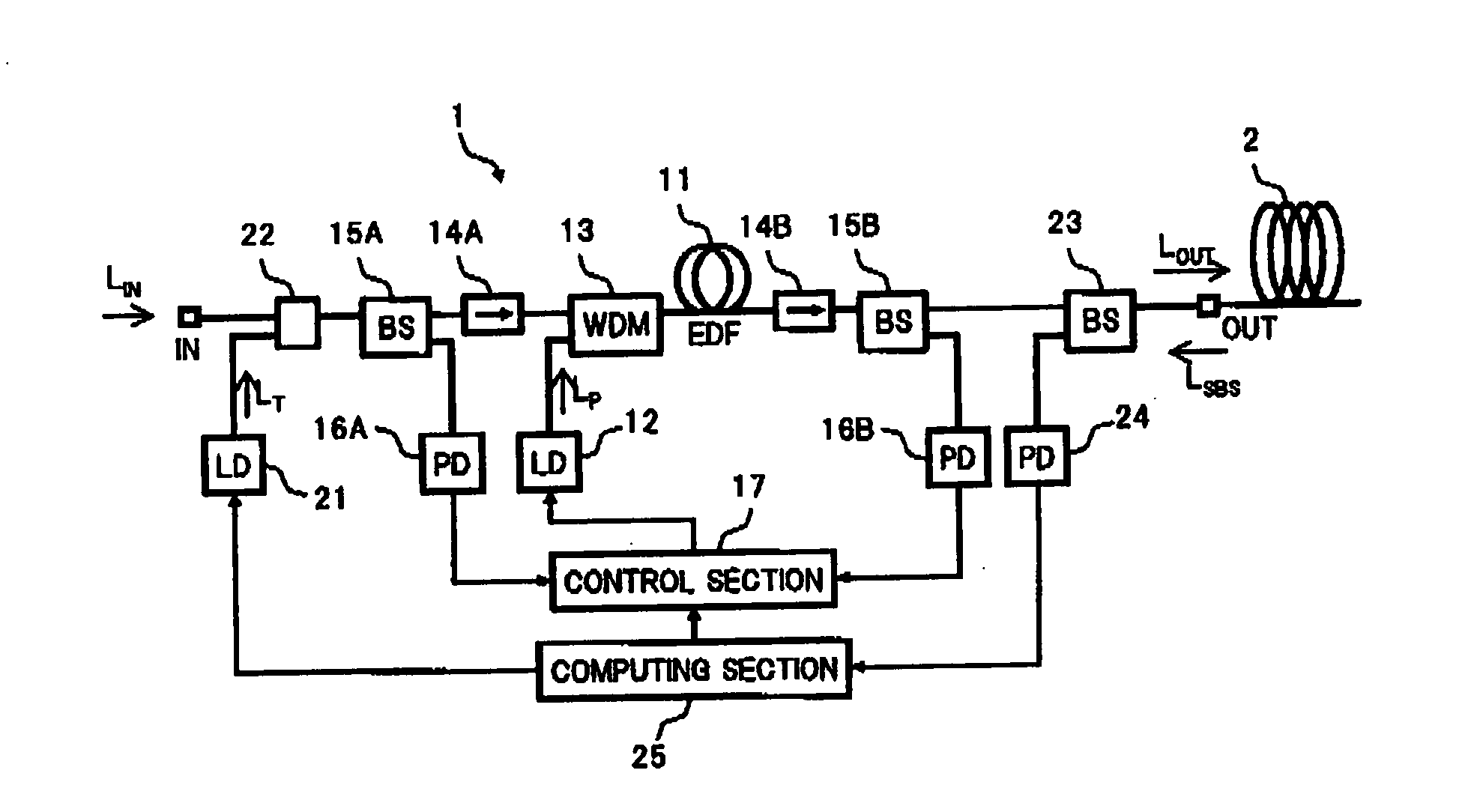
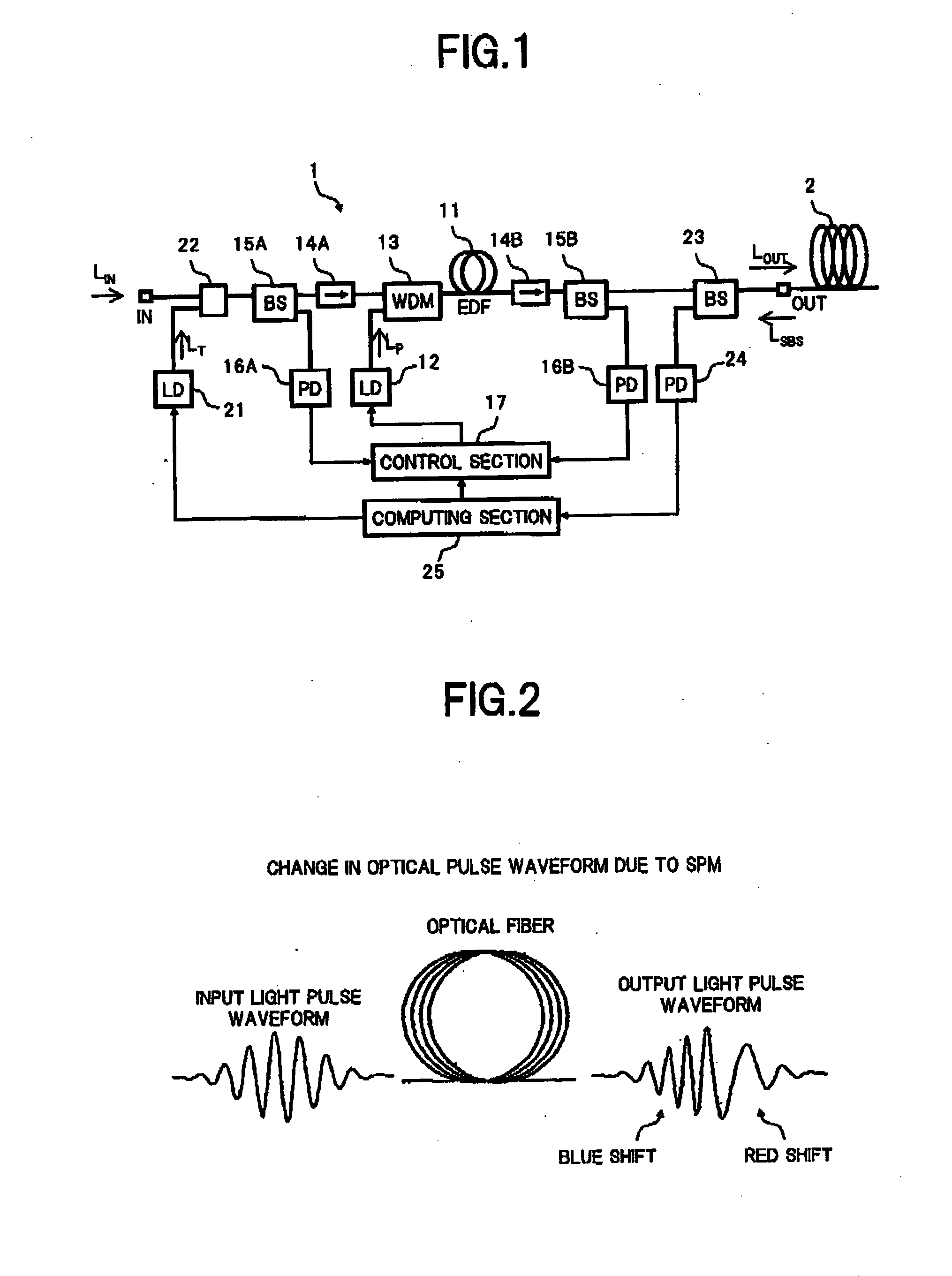
[0050]FIG. 1 is a block diagram showing a configuration of one embodiment of an optical amplifier using a measuring method of the nonlinear optical properties according to the present invention.

[0051]In FIG. 1, an optical amplifier 1 in the present embodiment is arranged with, for example, an erbium-doped fiber (EDF) 11 on an optical path between an input port IN and an output port OUT, and supplies a pumping light Lp output from a pumping light source 12 to the erbium-doped fiber 11 via a WDM coupler 13 from a signal light input end side. An input light LIN supplied to the input port IN is input via an optical isolator 14A and the WDM coupler 13, to the erbium-doped fiber 11 which is forwardly pumped by the pumping light Lp, and the light which has been propagated through the er...


PUM


Abstract

In an optical amplifier of the present invention, an input light is supplied to one end of an optical fiber connected to an output port, and the power of a light In an opposite direction which is input to the output port from the one end of the optical fiber, is measured, thereby obtaining a stimulated Brillouin scattering (SBS) occurrence threshold in the optical fiber based on the measurement result. Then, using the SBS occurrence threshold, a relation been the input light power and an occurrence amount of the self phase modulation (SPM) or the like in the optical fiber is obtained to be reflected on a control of the optical amplifier, so that an occurrence of the SPM or the like in the optical fiber is suppressed. As a result, It becomes possible to accurately measure, with a simple configuration, the nonlinear optical properties of the optical fiber actually connected to the output port of the optical amplifier, so that the optical S/N ratio degradation due to a nonlinear optical effect can be effectively suppressed.

Description

BACKGROUND OF THE INVENTION[0001]1. Field of the Invention[0002]The present invention relates to a method for measuring the nonlinear optical properties of various types of optical fibers to be used for optical communications, and an optical amplifier and an optical transmission system, each of which uses the method of measuring the nonlinear optical properties to control an optical input level to an optical fiber, thereby suppressing an occurrence of a nonlinear optical effect.[0003]2. Description of the Related Art[0004]In an optical transmission system, an optical amplifier is used for compensating for a transmission loss in an optical fiber or a loss in an optical function device. In a long-distance trunk system, with an increase of communication demand due to the spread of the internet, there is introduced a wavelength division multiplexing (WDM) optical transmission system which applies the broadband property of the optical amplifier. Further, a WDM optical transmission system...

Claims


Application Information

Patent Timeline
IPC IPC(8): H01S3/00G02F1/35H01S3/067H01S3/10H04B10/077H04B10/25H04B10/2507H04B10/2543H04B10/29H04B10/291
CPCG01M11/319H04B10/255G01M11/33
Inventor SHUKUNAMI, NORIFUMITSUZUKI, TATSUYA
Owner FUJITSU LTD
Why Eureka
Try Eureka