Steering laser treatment system and method of use

a laser treatment and steering technology, applied in the field of retinal laser treatment, can solve the problems of insufficient time for equipment turnaround, inability to achieve total treatment time in excess of 30 minutes, and inability to achieve the effect of reducing the time required, improving efficiency, and facilitating ophthalmic operations

Inactive Publication Date: 2008-01-17
MOTOROLA MOBILITY LLC
View PDF13 Cites 201 Cited by
  • Summary
  • Abstract
  • Description
  • Claims
  • Application Information

AI Technical Summary

Problems solved by technology

However, there is a practical limit for this repetitive treatment that depends on features of the SL, the type of contact lens being used, patient cooperation and the skill of the operator among others.
This means that the total treatment time can be in excess of 30 minutes, which is fatiguing to the patient and to the surgeon with reduced equipment turnaround time.
Also, laying down a uniform pattern of laser burns is difficult and the pattern is typically more random than geometric in distribution.
(U.S. Pat. No. 6,066,128) but have not reached clinical practice.
Also attempts have been made to automate the PRP process by experimenting with complex image analysis software and laser delivery systems but these have not reached the clinical field probably because they are not reliable or cost-effective.
It is a limitation of current slit lamp PRP methodologies the requirement for the operator to reposition the aiming beam onto a new target location each time a laser photocoagulation spot treatment has been placed over a single treatment location.
It is another limitation of current slit lamp PRP methodologies the difficulty in placing an about equally spaced geometrical pattern of laser energy treatment over a plurality of neighbor treatment locations.
It is an overall limitation of current slit lamp PRP methodologies the fact that it is a prolonged repetitive and fatiguing procedure for the operator and the patient.
It is a limitation of multiple beam SL delivery systems the need to multiply the available laser power to simultaneously treat a total larger area of the retina.
It is a limitation of multiple fiber SL systems simultaneously delivering laser power to a plurality of treatment locations the need for higher instantaneous laser powers with potential damage caused to light energy-sensitive ocular structures such as the crystalline lens and others, specially in the presence of opacities.
These high laser energy systems can irradiate the eye structures with energy levels above recommended safety thresholds with the potential of producing light toxicity to the eye of the patient and of the operator.
In fact, current SL protective filters could render inadequate to effectively block the more intense light entering the eye of the operator.
It is a limitation of automated image analysis based system proposals for PRP the need of expensive image capturing devices coupled to the SL.
It is another limitation of automated image analysis based system proposals for PRP the difficulty in obtaining a simultaneous wide field image of the fundus of the eye that is clear and stable.
In this sense, it is an unsolved limitation for these systems the fact that current PRP procedures typically require skillful manipulation of a focusing contact lens and of the SL illumination system to clearly expose, in a sequence, a wide area of the retina for adequate laser treatment.
It is an overall limitation of U.S. application No. 20060100677 that this system can only deliver spots of laser treatment in strict coincidence with spots forming a pre-positioned alignment pattern.
Providing an alignment pattern that substantially coincides with the treatment zones that will receive the therapeutic laser energy can over-expose the patient's retina to the operator fixation light and can promote involuntary patient gaze direction toward the treatment area with the potential of causing a laser injury onto the fovea resulting in central blindness.
It is still another limitation of U.S. application No. 20060100677 that this system can only apply spot shaped laser treatments onto the treatment locations.
It is still another limitation of the system described in U.S. application No. 20060100677 delivering square shaped patterns of distribution of the treatment locations non optimal by producing uneven distances between neighbor spots, instead of a more physiologic i.e. equidistant pattern, that allows better irrigation distribution and nerve conduction at the remaining retina between neighbor treatment locations.

Method used


Image

  • Steering laser treatment system and method of use
  • Steering laser treatment system and method of use
  • Steering laser treatment system and method of use

Examples


Embodiment Construction

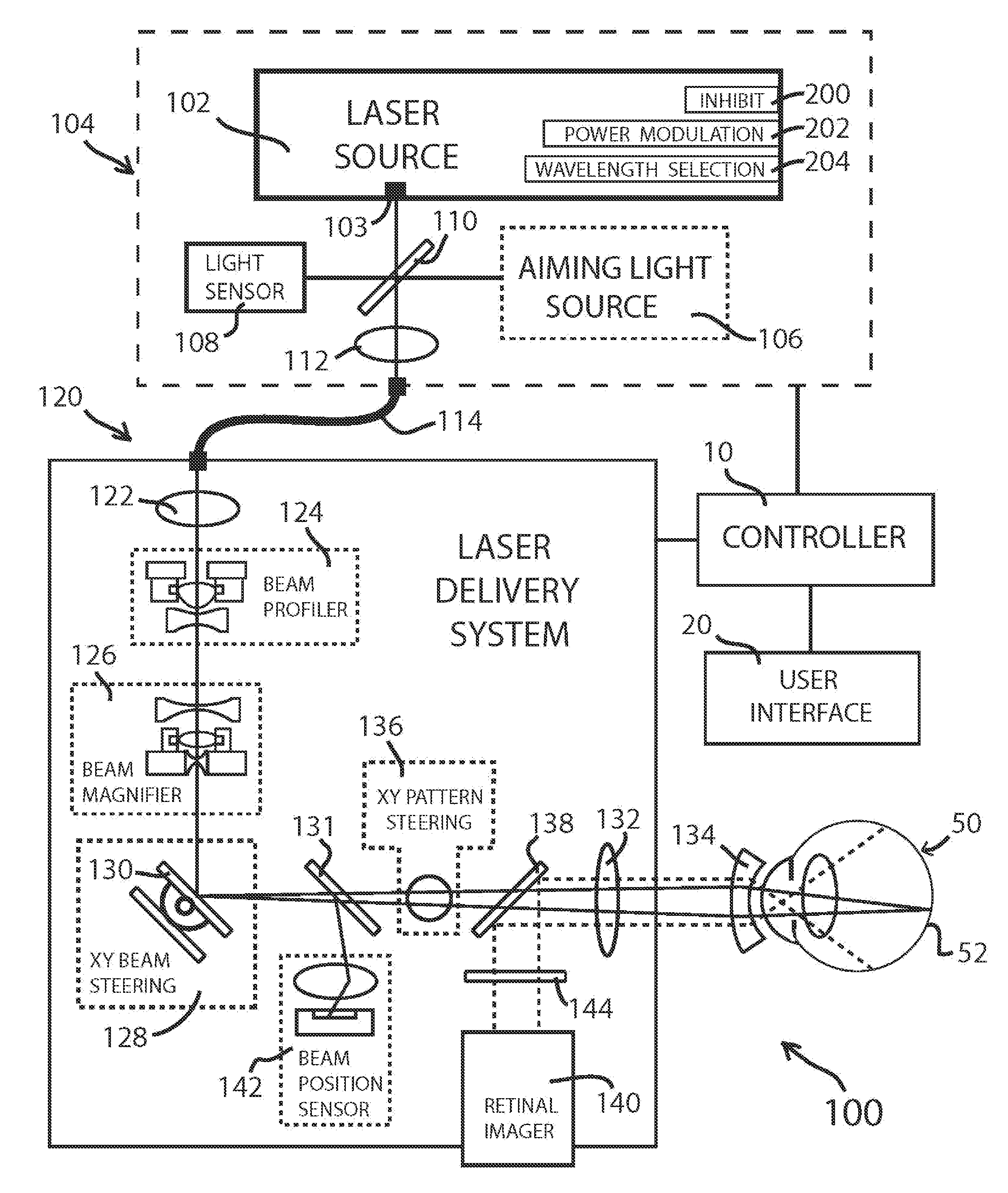
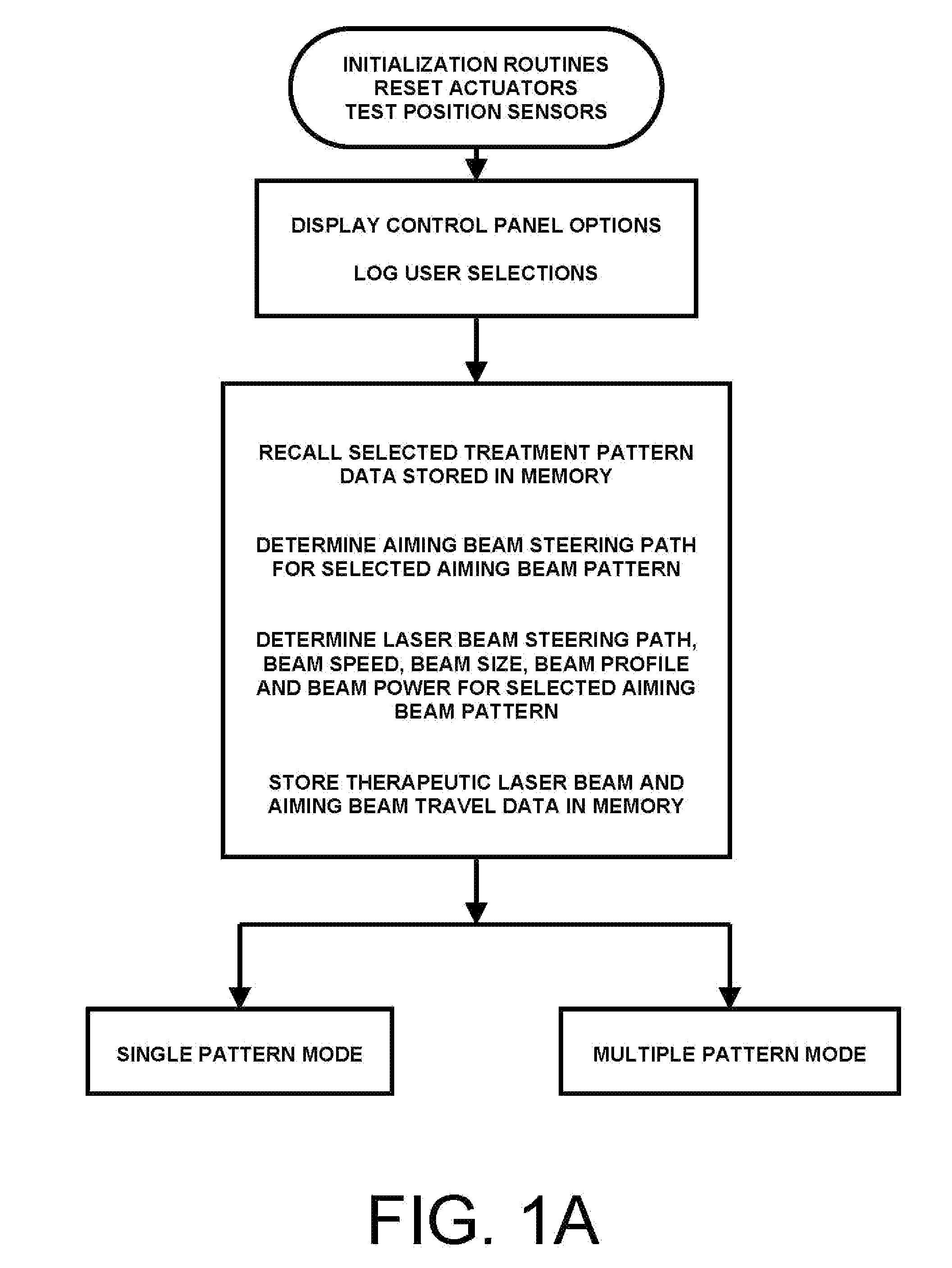
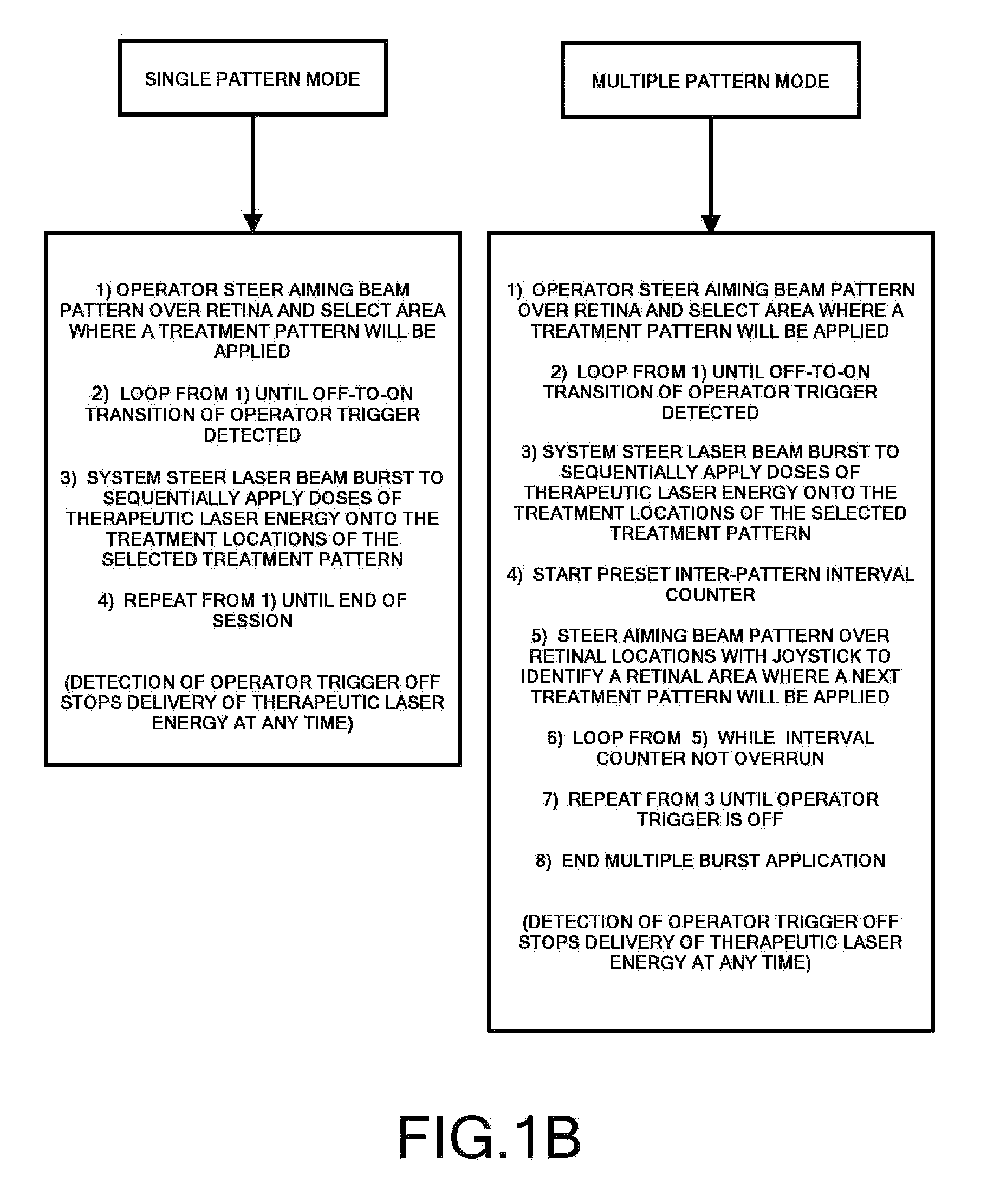
[0067]FIGS. 1A and 1B depict a flow diagram a method that can be practiced with the present invention. Generally speaking, the steps of this method consider setting the system for operation including making selections related to the planned treatment, having a processor / controller 10 process and store relevant data according to the operator selections, projecting an aiming beam pattern onto retinal areas, using said aiming beam pattern as a reference, selecting a treatment area of the retina where therapeutic doses of laser energy will be delivered over treatment locations disposed in the predetermined treatment pattern. The operator performs a triggering action having the system to deliver a rapid burst of modulated laser energy while rapidly steering the laser beam to obtain the desired pattern of treated locations on the retina.

[0068]The operator can adjust aspects of the selected pattern of treatment locations between applications, including repositioning, rotation, scaling, and...


PUM


Abstract

A system and method for delivering therapeutic laser energy onto selected treatment locations of the retina following a predetermined spatial distribution pattern using one single laser beam. A beam steering mechanism and control system delivers the laser energy sequentially to treatment locations forming a pre-selected treatment layout pattern. The invention allows time consuming therapeutic laser procedures such as pan-retinal photo-coagulation and segmental photocoagulation to be performed with increased accuracy and in a fraction of the time currently required for such procedures.

Description

BACKGROUND[0001]1. Field of the Invention[0002]The present invention relates to a modality of laser treatment for the retina, and more particularly, to the delivery of therapeutic doses of laser energy in a rapid sequence to affect a preset pattern of treatment locations during a single burst of laser activity.[0003]2. Description of Prior Art[0004]Laser retinal therapy is used for various ophthalmic conditions requiring therapeutic doses of retinal energy. One example of a multi-dose laser treatment for retinal disease is pan-retinal photocoagulation (PRP). These laser procedures are typically performed using laser delivery systems attached to retinal imaging systems such as a slit-lamp (SL). In most common slit-lamp systems, the laser energy is provided by a laser source to the imaging optics through an optical fiber. The imaging optics are commonly used in conjunction with a variety of contact lenses and are capable of focusing the laser energy exiting the output end of the optic...

Claims


Application Information

Patent Timeline
Patent Type & Authority Applications(United States)
IPC IPC(8): A61B18/20A61N5/067
CPCA61B2018/2085A61F2009/00863A61F9/008A61B2018/2272A61B2018/20351A61B2018/20361A61B2018/205545
Inventor ZACHARIAS, JAIME
Owner MOTOROLA MOBILITY LLC
Why Eureka
Try Eureka