Tool holder for a disc-shaped working tool

a technology of working tool and tool holder, which is applied in the direction of shearing tools, grinding machines, sawing apparatus, etc., can solve the problems of relatively time-consuming attachment or detachment of working tool discs, and achieve the effect of reducing manufacturing costs and simple manufacturing

Active Publication Date: 2008-01-24
HILTI AG
View PDF13 Cites 19 Cited by
  • Summary
  • Abstract
  • Description
  • Claims
  • Application Information

AI Technical Summary

Benefits of technology

[0015] This insures simple manufacturing of the shaped members and their attachment to the working tool holding members with conventional screws, which reduces manufacturing costs.
[0016] Advantageously, the at least one coupling element has a threaded bore in

Problems solved by technology

However, the attachment or detachment of the working tool disc is r

Method used


Image

  • Tool holder for a disc-shaped working tool
  • Tool holder for a disc-shaped working tool
  • Tool holder for a disc-shaped working tool

Examples


Embodiment Construction

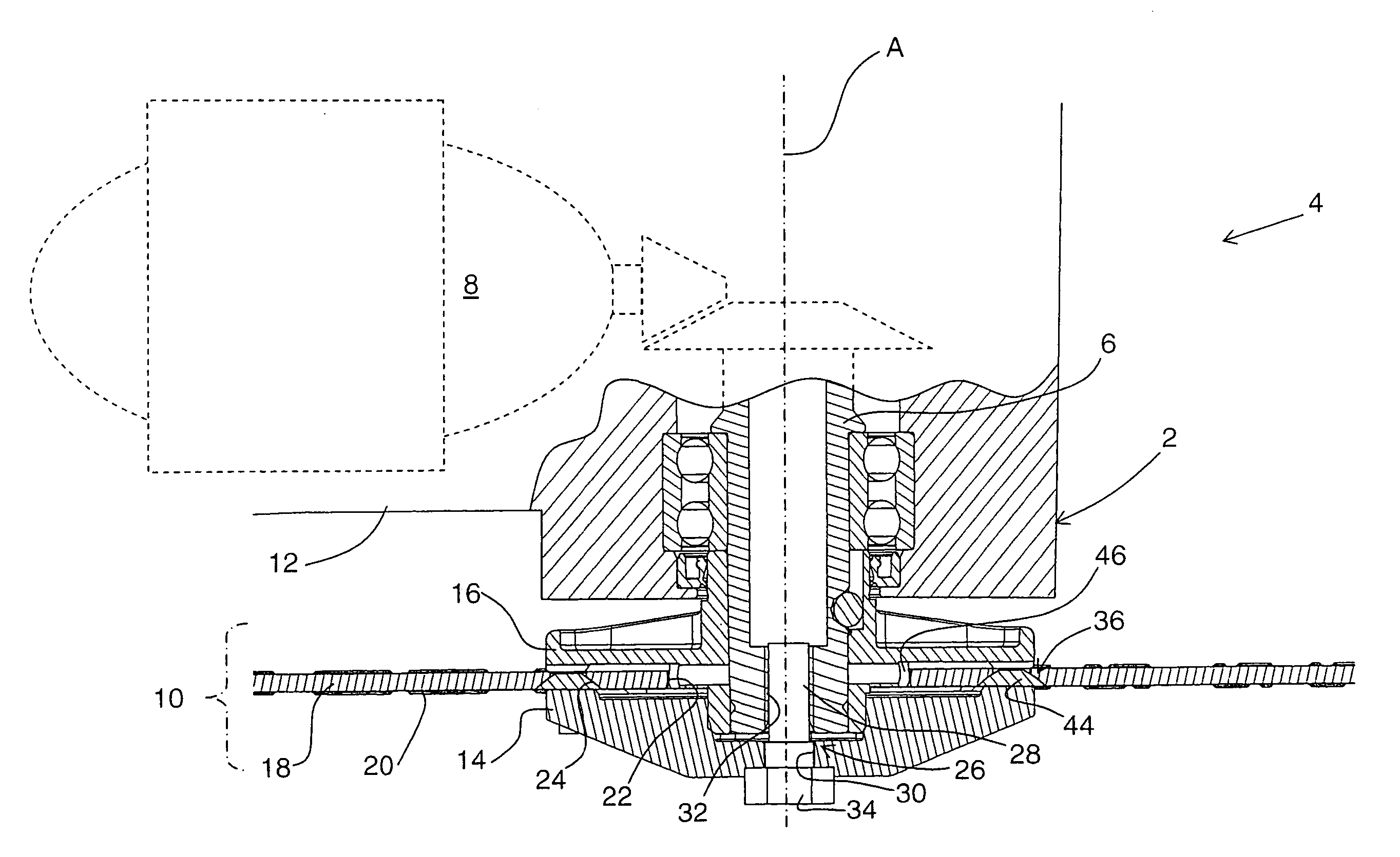
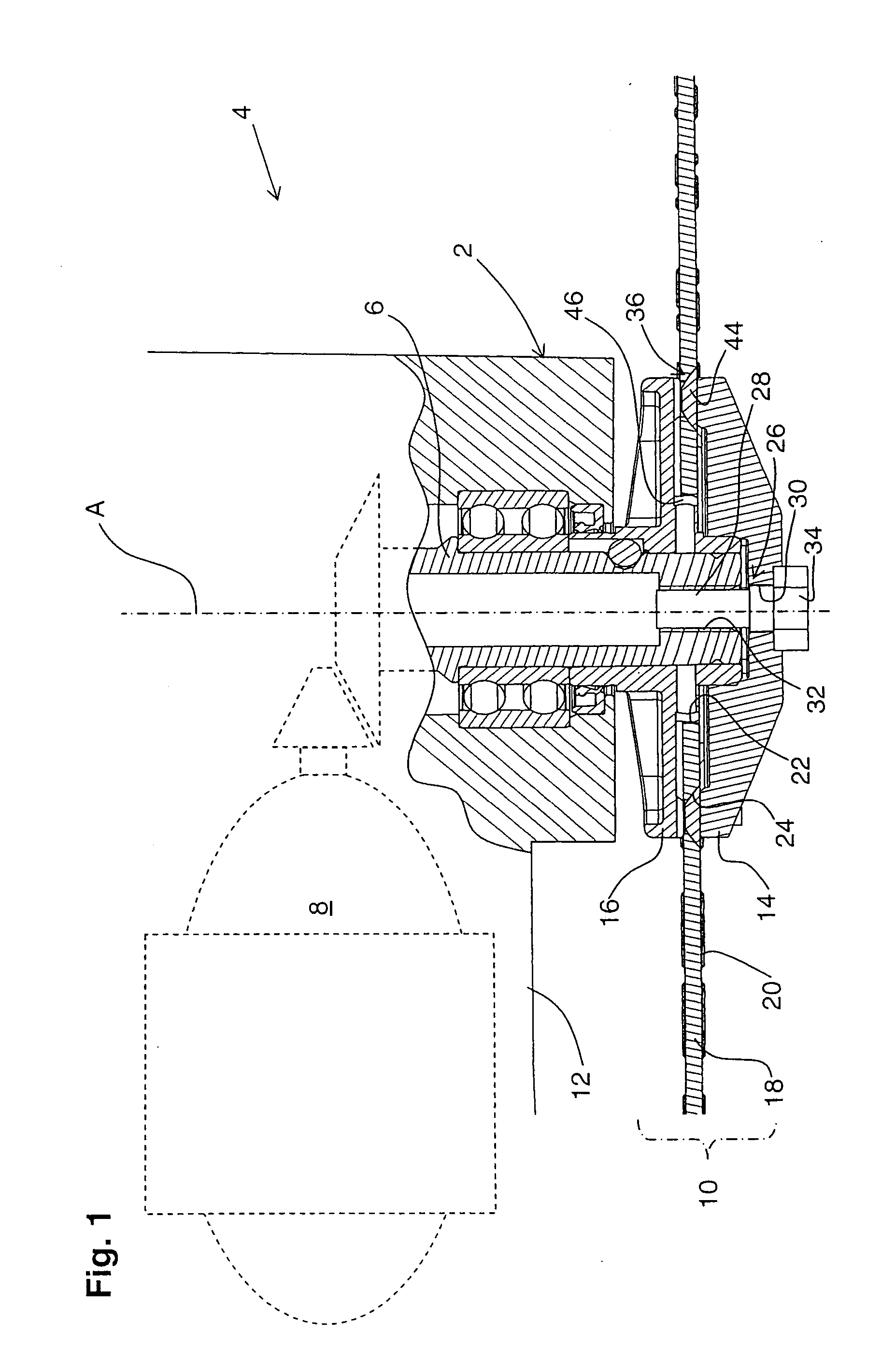
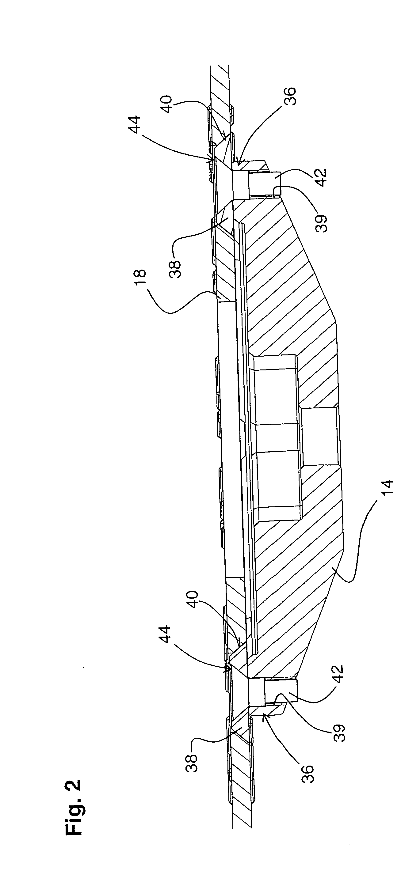
[0023]FIG. 1 shows a head 2 of a power tool 4 which is formed as an angle grinder. The power tool 4 has spindle-shaped output means 6 rotatable by a motor 8 about an operational axis A. A substantially two-part working tool holder 10 is supported on the output means 6. The working tool holder 10 has a flange-shaped working tool holding member 14 remote from the housing 12 of the power tool 4 and disc-shaped working tool holding counter-member 16 adjacent to the power tool housing 12. As shown in FIG. 1, a disc-shaped working tool 18, in particular an abrasive cutting disc, is secured between the working tool holding member 14 and the working tool holding counter-member 16.

[0024] The working tool 18, on which, e.g., diamond-studded cutting segments 20 can be provided, has a central bore 22 and six through-bores 24 radially spaced from the central bore 22. The through-bores 24 are formed as counter-bores the diameter of which is continuously tapered in the direction of the housing 12...


PUM


Abstract

A tool holder or a disc-shaped working tool (18) has a working tool holding member (14) and a working tool holding counter-member (16) rotatable, together with the working tool holding member, (14) about an operational axis (A) and cooperating with the working tool holding member (14) for receiving therebetween the working tool (18) for joint rotation therewith; central securing element (26) for securing the working tool (18) between the working tool holding member (14) and the working tool holding counter-member (16); and at least one coupling element (44) associated with the working tool holding member (14), radially spaceable from the central securing element (26) and having a rotary stop for forming a releaseable plug-in connection with at least one through-bore (24) formed in the working tool (18).

Description

BACKGROUND OF THE INVENTION [0001] 1. Field of the Invention [0002] The present invention relates to a tool holder for a disc shaped working tool such as, in particular, a cutting disc, e.g., an abrasive cutting disc. The tool holder has a working tool holding member and a counter-member rotatable, together with the working tool holding member, about an operational axis by a motor-driven power tool and cooperating with the working tool holding member for receiving therebetween the working tool for joint rotation therewith. The working tool has a central bore and at least two through-bores spaced from the central bore and each having a sharp-or continuously changing diameter over the bore length, such as, e.g., counter -or step-bores. The working tool holding member has a central opening through which in an assembled condition of the tool holder, a central securing element extends for axially securing the working tool holding member and, thereby, the working tool between the working ...

Claims


Application Information

Patent Timeline
IPC IPC(8): B26D1/12
CPCB23B31/4073B27B5/32B24B45/006Y10T83/9403
Inventor WEBER, CHRISTOPHHOOP, MATTHAEUS
Owner HILTI AG
Why Eureka
Try Eureka