Liquid Crystal Display Device

a liquid crystal display and liquid crystal technology, applied in the direction of liquid crystal compositions, instruments, chemistry apparatus and processes, etc., can solve the problems of limited time required for the change of the orientation direction of the liquid crystal molecules, deterioration of the moving picture quality, and considered problems, and achieve good moving picture quality and difference in response time

Inactive Publication Date: 2008-01-24
HITACHI LTD
View PDF6 Cites 16 Cited by
  • Summary
  • Abstract
  • Description
  • Claims
  • Application Information

AI Technical Summary

Benefits of technology

[0022]FIG. 1 is a graph showing the relationship between the viscosity and Δε of a liquid crystal compound or a liquid crystal composition. In FIG. 1, the plot shown by Δ indicates physical properties of compounds having a typical example of the structure specified in the first aspect of the invention. These compounds have a viscosity of about 100 mPa·sec. On the other hand, the viscosity of liquid crystal compounds and liquid crystal compositions in the case of the plot shown by  tends to decrease with a decrease of Δε, and the viscosity is decreased substantially to the utmost limit when |Δε|≦2. That is, by combining the compound having a typical example of the structure specified in the first aspect of the invention with the liquid crystal compound satisfying the inequality |Δε|≦2, the viscosity of the resulting composition can be reduced most efficiently.
[0035]According to the present invention, a good moving picture quality can be attained as follows irrespective of a liquid crystal display method such as VA method or IPS method: when the response time of liquid crystals is different in different pixels or nonuniform in one and the same pixel, as in a liquid crystal display device in which the thickness of a liquid crystal layer is different in different pixels or nonuniform in one and the same pixel, a difference in the response time made by a temperature lowering is reduced, or a difference in the response time between a high-temperature portion and a low-temperature portion is reduced which is made when the surface temperature of the display screen of the liquid crystal display device is not uniform.

Problems solved by technology

However, a limited time is required for the change in the direction of orientation of the liquid crystal molecules after the application of the electric field.
When this time (=response time) is long, the moving picture quality is deteriorated.
This is considered a problem.
That is, when a liquid crystal composition having a high viscosity is used, the speed of response is low.
Such temperature dependence of the viscosity of the liquid crystal composition becomes a more important problem when the employment of the composition in a device is investigated.
Therefore, it is difficult to make the temperature in the liquid crystal display screen uniform, so that a temperature distribution exists in a plane of the liquid crystal layer.
When the technique for thus controlling the backlight in each region is adopted, the following problem is caused: the temperature distribution in a plane of the liquid crystal layer becomes remarkable, so that the speed of response is changed in every region in the display screen in the case of a liquid crystal composition having much temperature dependence, resulting in a deteriorated moving picture display.
If the viscosity of the liquid crystal composition changes markedly with temperature, such a liquid crystal display device is disadvantageous in that moving picture characteristics in each region change markedly with temperature.
The above-mentioned problems, i.e., the partial deterioration of the moving picture quality by the temperature non-uniformity in the display screen and the widening of the difference in moving picture quality between regions different in the thickness of the liquid crystal layer during low-temperature operation, are caused by the temperature dependence of the response time, i.e., the temperature dependence of the viscosity of a liquid crystal material.
These problems are common to all liquid crystal display devices in which a display is given by the use of the electroopitical characteristics of a liquid crystal material, such as liquid crystal display devices in which an electrode is located on each of upper and lower substrates and an electric field substantially perpendicular to the substrate surface is applied and which are represented by liquid crystal display devices according to the twisted nematic (TN) method, vertical alignment (VA) method or electrically controlled birefringence (ECB) method; and liquid crystal display devices according to in-plane switching (IPS) method, a display method in which an inter digital electrode is located on one of upper and lower substrates, the direction of application of an electric field is made substantially parallel to the in-plane direction of the substrate and the change of the birefringence of liquid crystals is utilized.

Method used


Image

  • Liquid Crystal Display Device
  • Liquid Crystal Display Device
  • Liquid Crystal Display Device

Examples


example 1

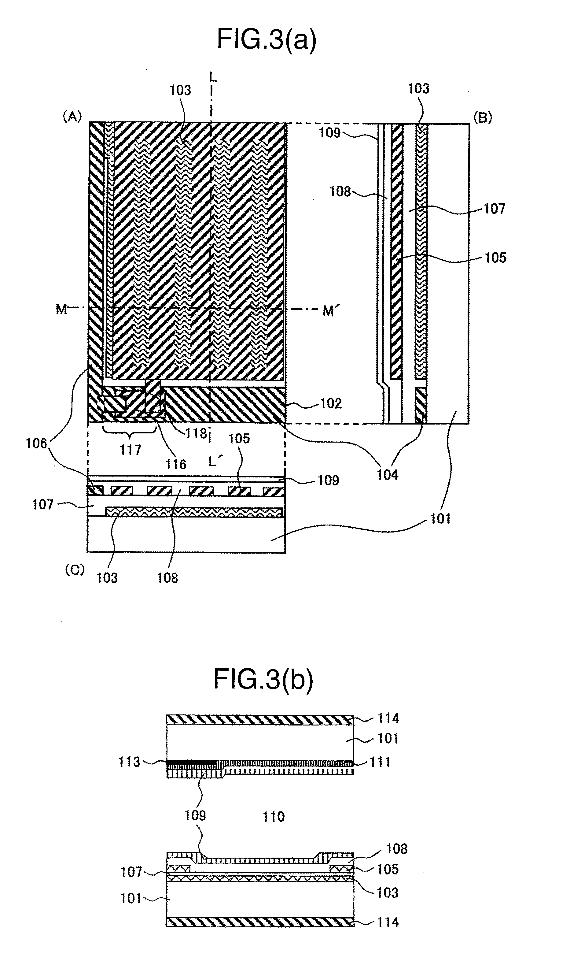
[0054]A first working example is explained below in detail with reference to FIG. 3(a) and FIG. 3(b).

[0055]In the production of a liquid crystal display device as the first working example of the present invention, a 0.7-mm thick glass substrate having a polished surface was used as each of a glass substrate 101 that constitutes an active-matrix substrate and another glass substrate 101 that constitutes an opposite substrate (a color filter substrate). Thin-film transistors 117 formed on the glass substrate 101 were composed of a pixel electrode wiring 118, a signal electrode 106, a scanning electrode 104 and a semiconductor film 116. A common electrode 103 and the pixel electrode wiring 118 were formed by patterning ITO, and all of the scanning electrode 104, a common electrode wiring 102 and the signal electrode 106 were formed by patterning a chromium film. An insulating film 107 and a protective film 108 were made of silicon nitride and the thickness of each of them was adjusted...

example 2

[0066]In the same manner as in the case of the liquid crystal display device described in Example 1, an active-matrix substrate and an opposite substrate having a color filter formed thereon were produced and then assembled. Then, compounds represented by the formulas 2 and 3 were added as typical examples of the liquid crystal compound specified in the fifth aspect of the invention to the same liquid crystal composition as used in Example 1, each in an amount of about 10% by weight, and the liquid crystal composition thus prepared was injected into the assembly obtained above, by vacuum enclosing. The liquid crystal display panel thus obtained was held between two polarizing plates 114. The polarizing plates 114 were located so that the axis of transmission of polarized light of one of the polarizing plates might be substantially parallel to the above-mentioned direction of liquid crystal molecular orientation and that the axis of transmission of polarized light of the other polari...

example 3

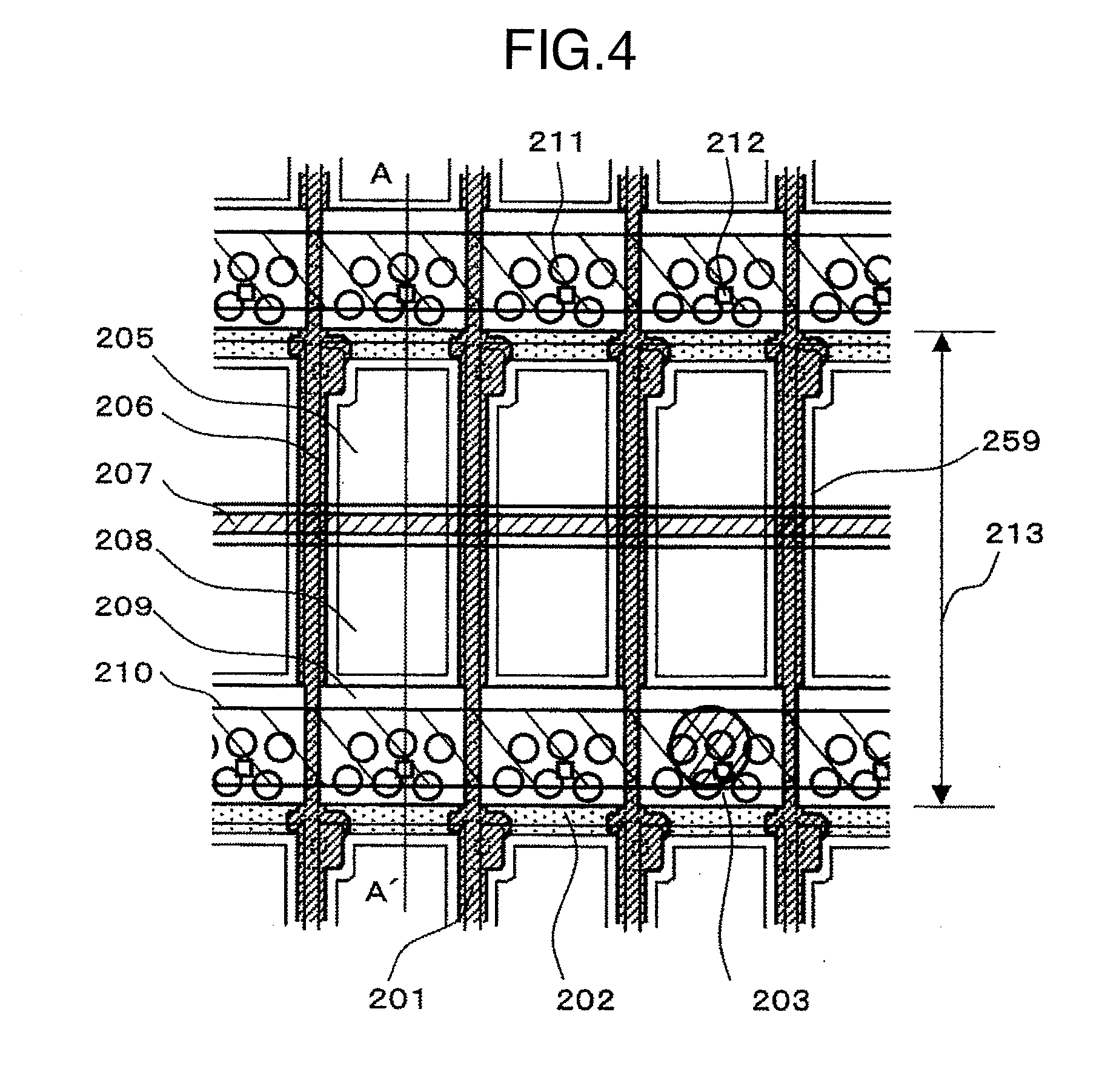
[0068]The structure of a liquid crystal display device of a working example according to the seventh to thirteenth aspects of the invention is explained below with reference to FIG. 4, FIG. 5 and FIG. 6. Although ECB display method was chosen in Example 3 unlike in Example 1 in which IPS method was adopted, other display methods such as IPS method, VA method and TN method may be chosen.

[0069]FIG. 4 is a plan view of the liquid crystal display device of the present example, which includes three pixels and their peripheral regions in a display region where pixels are located in the form of a matrix.

[0070]FIG. 5 is a sectional view taken along the line A-A′ of FIG. 4.

[0071]The plan view as FIG. 4 shows the location of the following: a backlight (not shown), a second substrate 215, a liquid crystal layer 221 and a first substrate 214 which are located in that order in the direction from the background to the foreground.

[0072]The first substrate 214 has the following components formed th...


PUM

PropertyMeasurementUnit
electric fieldaaaaaaaaaa
thicknessaaaaaaaaaa
structureaaaaaaaaaa

Abstract

The present invention is intended to provide a liquid crystal display device excellent in moving picture characteristics in view of the temperature dependence of the viscosity of a liquid crystal composition. In the present invention, one or more compounds having the following structure are used in the liquid crystal composition in the liquid crystal display device having a predetermined structure (in the following formula, each of X1 and X2 is an alkyl group, an alkenyl group, an alkoxy group, an alkenyloxy group, a substituent formed by fluorination of any of these groups, a halogen atom, a cyano group, a nitro group or an isothiocyano group; Ps are independently a fluorine atom, a hydrogen atom or an alkyl group; A and B are independently —CF2O—, —CH2CH2—, —CH2O— or —CF2—CH2— which have a structure comprising single bonds; each of Z1, Z2 and Z3 is a molecular group comprising a 6-membered ring and selected from a benzene ring, a cyclohexane ring, a fluorinated benzene ring and a fluorinated cyclohexane ring; each of m and o is 0 or 1; and n is 1 or 2):

Description

BACKGROUND OF THE INVENTION[0001]The present invention relates to a liquid crystal material, more particularly, a liquid crystal display device improved in moving picture quality.[0002]In liquid crystal display devices, an electric field is applied to liquid crystal molecules in a liquid crystal layer inserted between a pair of substrates and a display is given by utilizing a change in the optical properties of the liquid crystals caused by a change in the direction of orientation of the liquid crystal molecules caused by the application of the electric field. Such liquid crystal display devices are commonly used as the display portions of large-sized liquid crystal TV, monitors for PC, medium- or small-sized car navigation systems, mobile phones and PDA. However, a limited time is required for the change in the direction of orientation of the liquid crystal molecules after the application of the electric field. When this time (=response time) is long, the moving picture quality is ...

Claims


Application Information

Patent Timeline
Patent Type & Authority Applications(United States)
IPC IPC(8): C09K19/00
CPCC09K19/20C09K19/42C09K2019/0466G02F1/133555C09K2019/3009G02F1/133371C09K2019/3004
Inventor TAKEDA, SHINTARO
Owner HITACHI LTD
Why Eureka
Try Eureka