
Method of manufacturing a polarizing plate, and a cutting mat used in the method

a technology of polarizing plate and cutting mat, which is applied in the direction of polarizing elements, instruments, optics, etc., can solve the problems of reducing the level of lowering in the part, affecting the performance of the part, and affecting the quality of the part, so as to reduce the level of lowering and the effect of high elastic modulus

Inactive Publication Date: 2008-01-24
NITTO DENKO CORP
View PDF0 Cites 0 Cited by
  • Summary
  • Abstract
  • Description
  • Claims
  • Application Information

AI Technical Summary

Benefits of technology

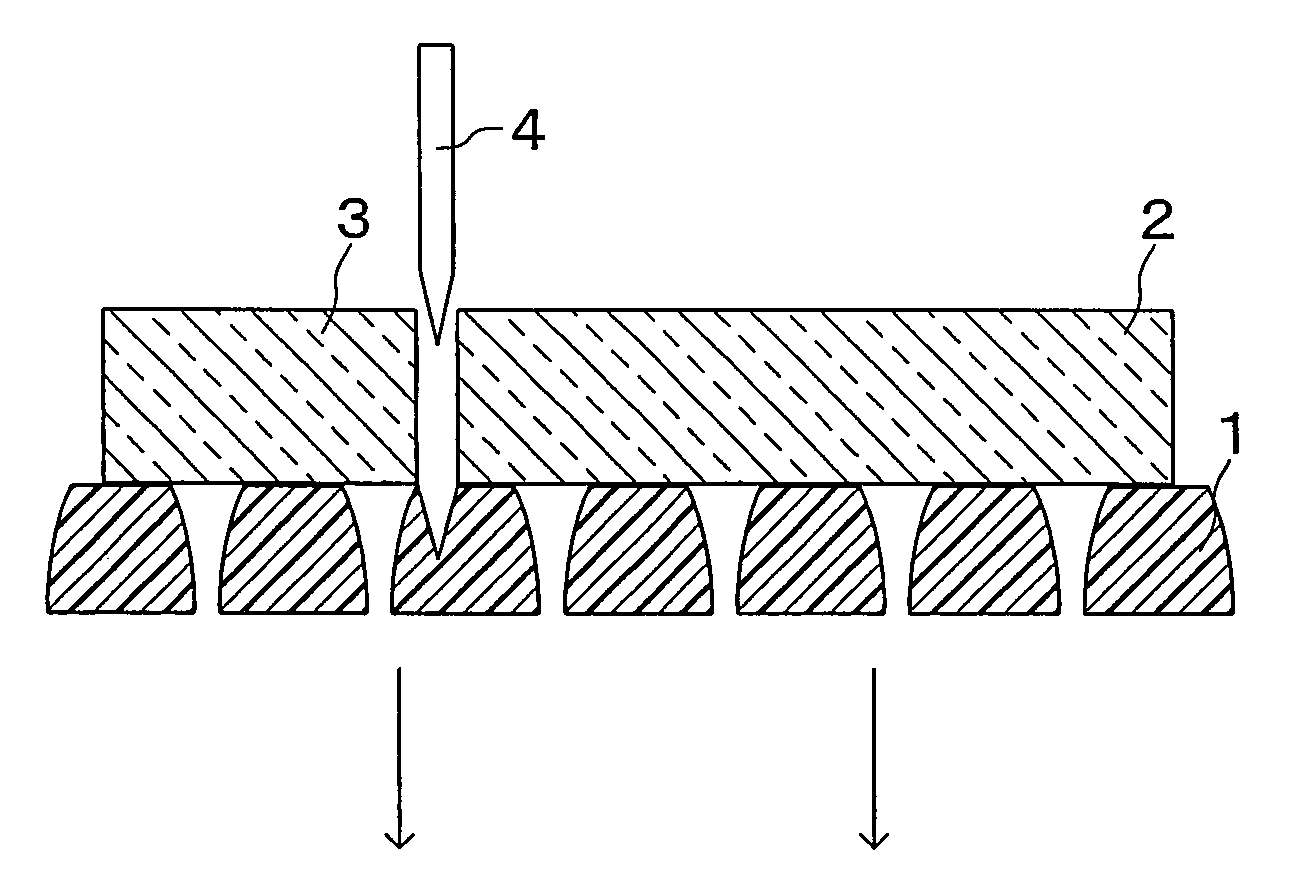
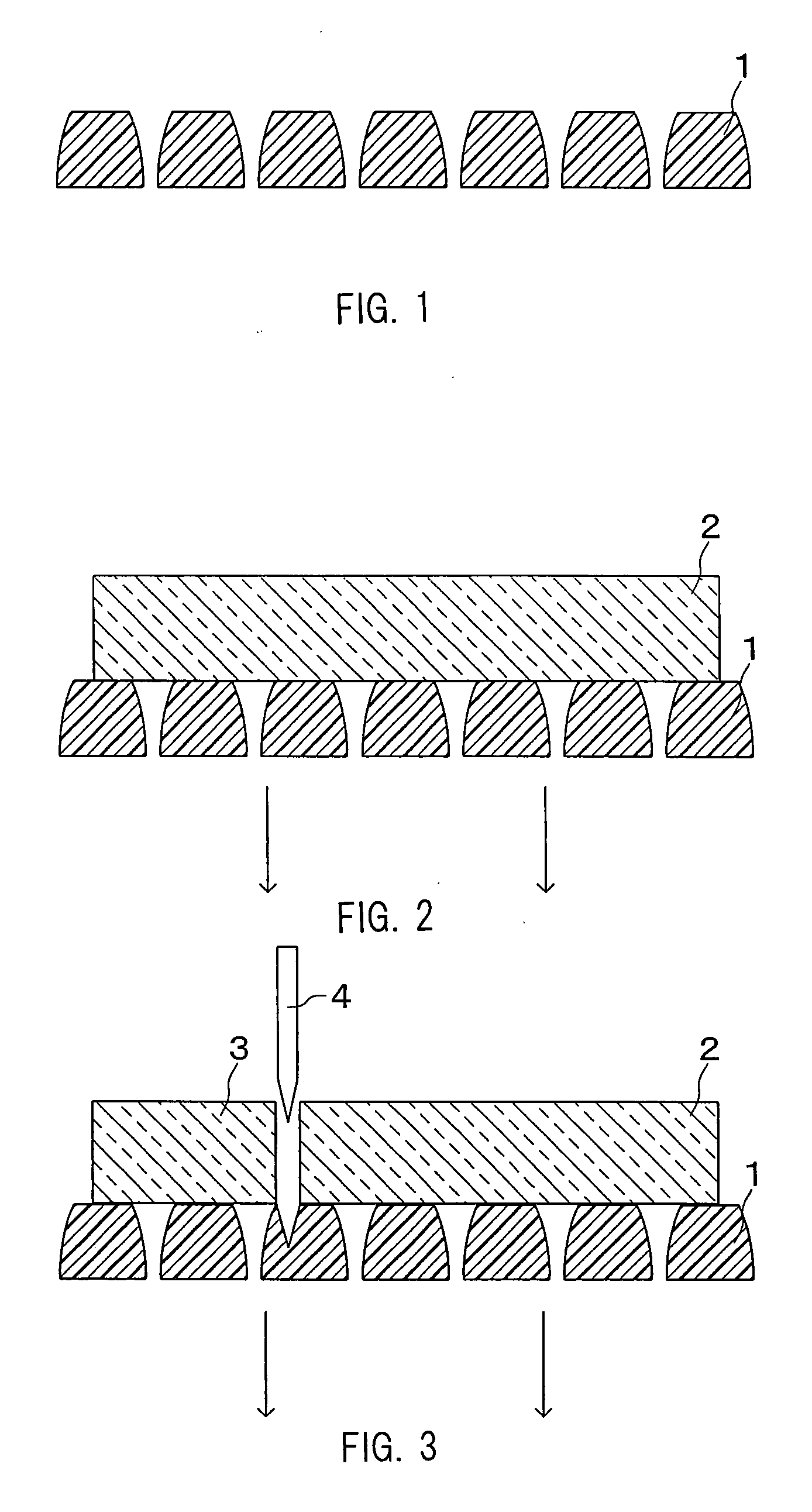
[0016]Moreover, ultrahigh molecular weight polyethylene porous sheets have a high elastic modulus (compressive modulus). When a blade presses a part of an original polarizing plate, such property enables reducing the level of lowering in the part. As the lowering level is reduced, an edge of the original plate can be inhibited from raising. Thus, according to the manufacturing method of the present invention, it becomes possible to improve accuracy in cutting dimension and inhibit the extension of cracks in a section.

Problems solved by technology

However, there is a problem when they are used as a cutting mat, due to paper particles or fibers being attached on the polarizing plate in the case of paper or nonwoven fabric, respectively.
When using paper, particular problems may result from impurities mixed from liquid pulp for making paper and foreign substances reclaimed with waste paper.
When using nonwoven fabric, problems may be caused by paraffins added as extrusion aids and antioxidants.
These attached substances may cause display defects or display distortion in a liquid crystal displaying device in which the polarizing plate is installed.
However, it causes a problem due to swarf remaining from the pore-making process being attached on the polarizing plate similar to the paper particles from paper and the fibers from nonwoven fabric.

Method used


Image

  • Method of manufacturing a polarizing plate, and a cutting mat used in the method
  • Method of manufacturing a polarizing plate, and a cutting mat used in the method

Examples


example 1

[0029]An ultrahigh molecular weight polyethylene porous sheet (“SUNMAP” manufactured by Nitto Denko Corporation; viscosity average molecular weight of six million, compressive modulus of 250 kgf / cm2, average pore diameter of 17 μm, thickness of 0.3 mm, Shore hardness of 48, coefficient of dynamic friction of 0.08) is prepared as a cutting mat to fix a four-layered original polarizing plate on the porous sheet. The original polarizing plate was fixed by drawing the original polarizing plate through the porous sheet from under the porous sheet.

[0030]Subsequently, a guillotine blade (a single blade) having an angle on the edge at 25 degrees was moved from above the original polarizing plate through it at a speed of 50 mm / second for cutting the original polarizing plate. At this point, the guillotine blade was moved to have the edge reach the depth of 0.1 mm below a surface of the porous sheet. This operation was repeated to make cutting plane lines on the original polarizing plate para...

example 2

[0032]Ultraviolet curable ink (“Daicure Ink” manufactured by Dainippon Inc and Chemicals, Inc.) was impregnated in vacant pores in the same ultrahigh molecular weight polyethylene porous sheet used in the Example 1. The ultraviolet curable ink was cured by irradiation of an ultraviolet lamp to obtain an ink impregnated porous sheet. By the same process as the Example 1 other than employing this ink impregnated porous sheet as a cutting mat, ten polarizing sheets were obtained. In addition, the maximum crack depth developed in the section of the polarizing plates, a cutting dimension error and appearance were evaluated in the same way as the Example 1. Results of the evaluation are shown in Table 1.


PUM

PropertyMeasurementUnit
thicknessaaaaaaaaaa
pore diameteraaaaaaaaaa

Abstract

A method of manufacturing a polarizing plate in which an original polarizing plate is cut accurately, cracks are not extended easily in a section and foreign substances are not attached easily on a polarizing plate to be obtained, and a cutting mat to be used in the method are provided. An original polarizing plate having a plurality of layers is fixed on a first principal surface of an ultrahigh molecular weight polyethylene porous sheet by drawing from the opposite side. The original polarizing plate is cut by a blade moving across the thickness of the original polarizing plate by using the porous sheet as a cutting mat to obtain a polarizing plate having a plurality of layers. A curable liquid, such as ultraviolet curable ink, is impregnated in vacant pores of the porous sheet, and is cured to obtain a sheet. The sheet thus obtained is particularly suitable for a cutting mat.

Description

BACKGROUND OF THE INVENTION[0001]1. Field of the Invention[0002]The present invention relates to a method of manufacturing a polarizing plate by cutting an original polarizing plate having a plurality of layers and it further relates to a cutting mat used in the method. In this specification, an original polarizing plate is defined as a polarizing plate before cutting so that it can be distinguished from a polarizing plate after cutting.[0003]2. Related Background Art[0004]A polarizing plate installed in a liquid crystal displaying device may be manufactured by cutting an original polarizing plate into a predetermined size, depending on the intended size. An original polarizing plate and a polarizing plate generally have a plurality of layers to provide various functions. Rotary blades are not suitable for cutting an original polarizing plate for such reasons that cutting with them requires a cutting margin, swarf from the cutting easily attaches to products due to static attraction...

Claims


Application Information

Patent Timeline
Patent Type & Authority Applications(United States)
IPC IPC(8): G02B27/28G02B5/30
CPCG02B5/3025B26D7/20G02B5/30B26D1/00
Inventor MORIYAMA, JUNICHI
Owner NITTO DENKO CORP
Learn More