Optical recording method, optical recording apparatus, optical recording medium, optical reproducing method, and optical reproducing apparatus

a recording apparatus and recording method technology, applied in the direction of optical recording/reproducing/erasing methods, instruments, flat record carrier containers, etc., can solve the problems of limiting the increase in recording capacity, uneven consumption of recording layer materials through the thickness of recording layers, and no more recording is available in the area where material is exhausted, etc., to achieve high recording density, increase recording capacity, and efficient

Inactive Publication Date: 2008-01-24
FUJIFILM CORP
View PDF4 Cites 4 Cited by
  • Summary
  • Abstract
  • Description
  • Claims
  • Application Information

AI Technical Summary

Benefits of technology

[0013] The present invention resolves the above conventional problems and has the objective of providing an optical recording method and an optical recording apparatus for holographically recording information in which uneven consumption of the material through the thickness of the recording layer during recording is reduced so as to achieve a high recording density and an increased recording capacity, an optical recording medium for recording by the optical recording method so that information recorded in a large volume and at high density is reproduced with efficiency, and an optical reproducing method and an optical reproducing apparatus for reproducing information recorded by the optical recording method in an efficient and excellent manner.
[0016] In the above optical recording method, at least one of the information beam and the reference beam is divided into two or more between the light source of the information beam and reference beam and the optical recording medium and the optical path lengths of the divided information beams and reference beams are adjusted so that they focus on points different from each other through the thickness of the recording layer, whereby the light density is distributed and one piece of recording information is divided and recorded in multiple regions through the thickness of the recording layer. Because of the light density distributed, each recording region has a low light density; therefore, differences in consumption of the recording layer material between the positions through the thickness are reduced and excessive consumption of the recording layer material per one recording is prevented. Intervals between adjacent holographically recorded images can be reduced, while increasing the recording density.

Problems solved by technology

However, the above multiple recording along with the horizontal movement allows for forming only one interference fringe through the thickness of the recording layer, limiting an increase in recording capacity.
Therefore, the recording layer material is subject to uneven consumption through the thickness of the recording layer.
Furthermore, no more recording is available in the area where the material is exhausted.
A limitation is imposed in increasing the recording capacity.

Method used


Image

  • Optical recording method, optical recording apparatus, optical recording medium, optical reproducing method, and optical reproducing apparatus
  • Optical recording method, optical recording apparatus, optical recording medium, optical reproducing method, and optical reproducing apparatus
  • Optical recording method, optical recording apparatus, optical recording medium, optical reproducing method, and optical reproducing apparatus

Examples


specific example of embodiment

[0199]FIG. 2 is a schematic cross-sectional view showing the structure of an optical recording medium 23 of a specific example of embodiment of the present invention. The optical recording medium 23 has a polycarbonate resin or glass substrate 1, on the surface of which an aluminum, gold, or platinum reflection film 2 is provided. Here, a servo pit pattern can also be provided on the surface of the substrate 1. In FIG. 2, the arrow indicates the circumferential direction of the optical recording medium 23.

[0200] When the above described gap layer is formed in this specific example of embodiment, the gap layer can be formed by applying a material such as an ultraviolet curable resin on the reflection film 2 of the second substrate 1, for example, by spin coating. The gap layer protects the reflection film 2 and is useful to adjust the size of hologram generated in the recording layer 4. In other words, the recording layer 4 has to have a region of a certain size for interference bet...

embodiment 1

of Optical Recording and Reproduction

[0249] Embodiment 1 of the optical recording method of the present invention and optical reproducing method of the present invention using the optical path length adjusting unit is described hereafter with reference to the drawing.

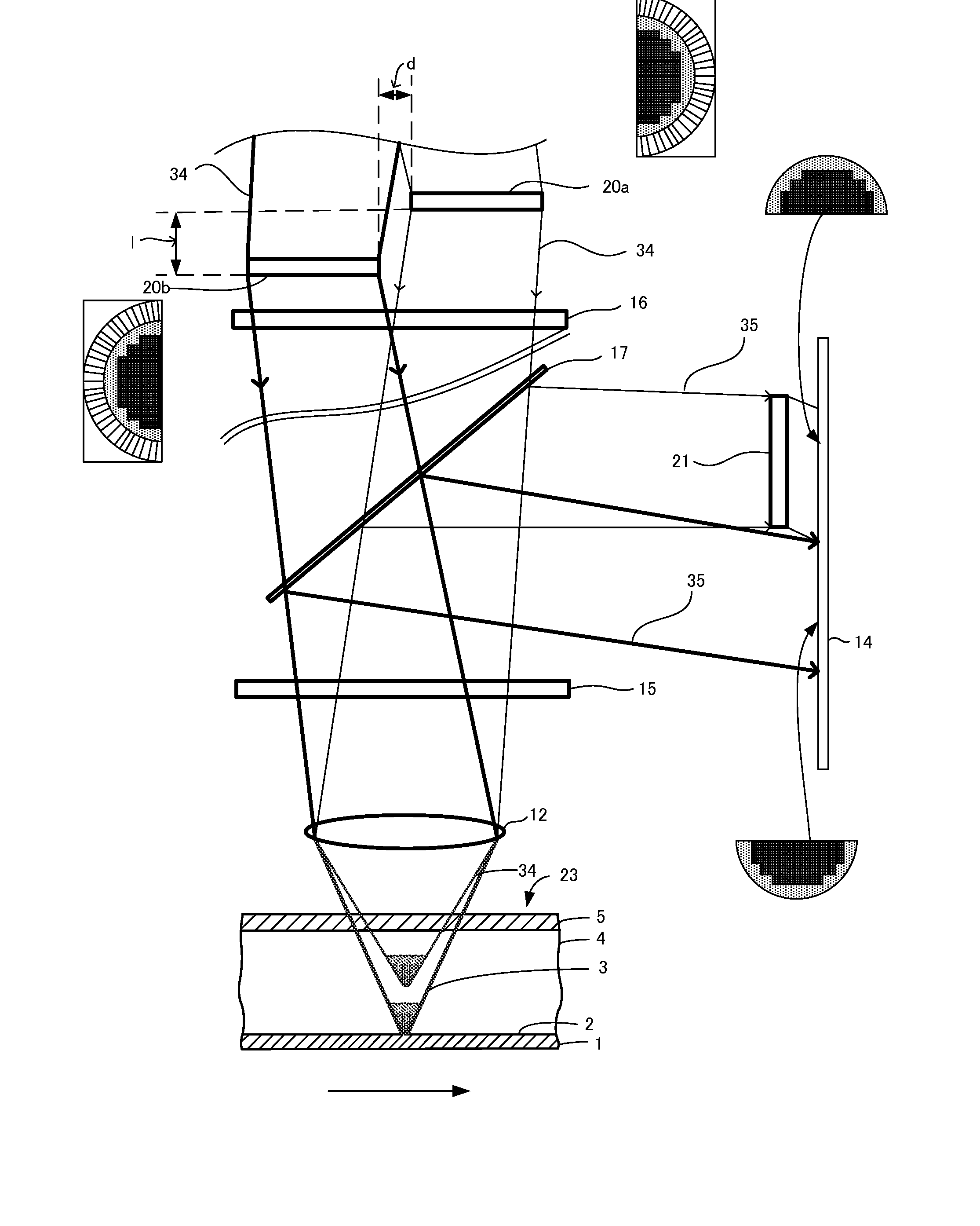
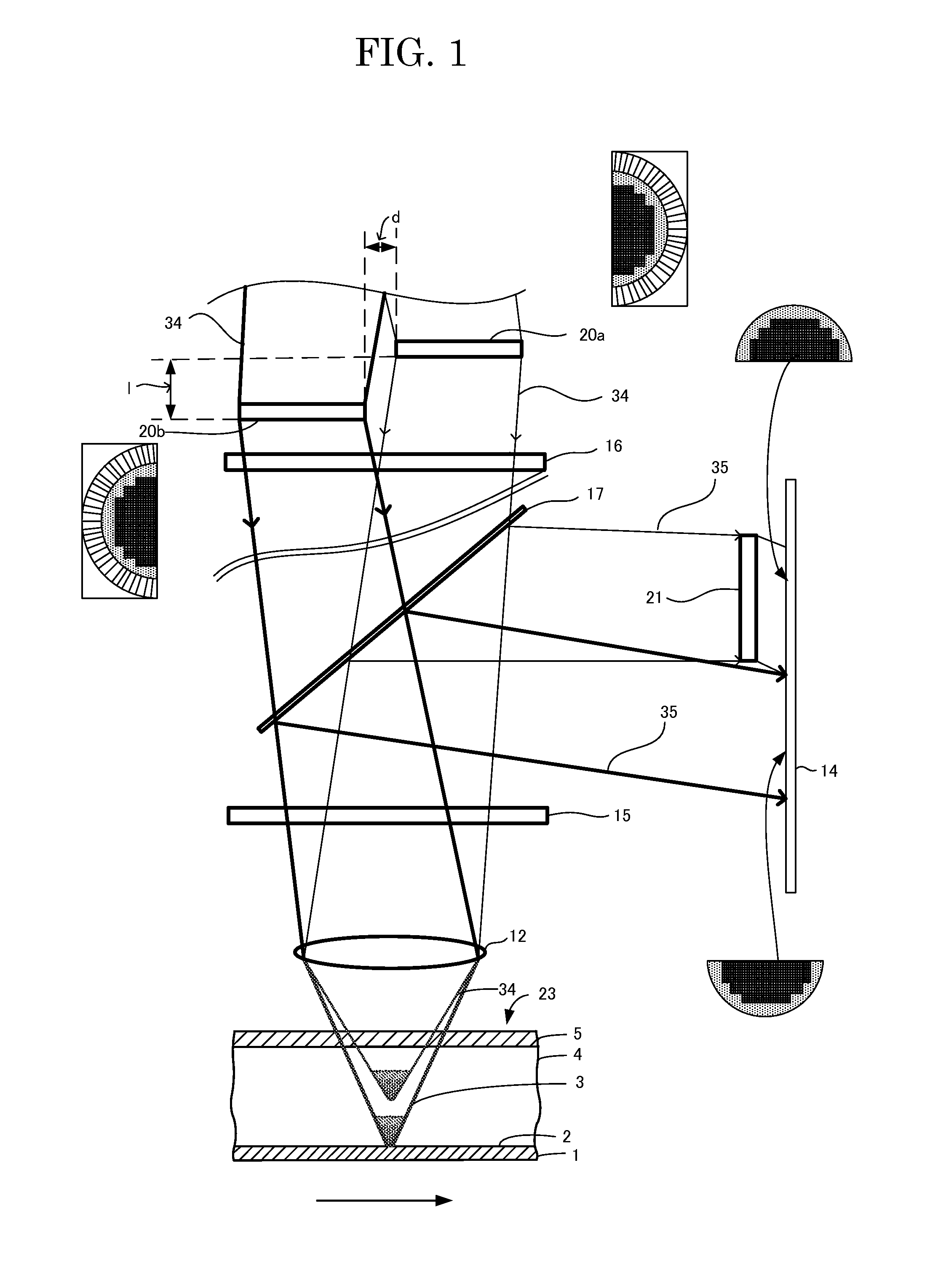
[0250] In Embodiment 1, as shown in FIG. 1, two spatial light modulators 20a and 20b are provided between a light source (not shown) of the information beam and the reference beam and reproduction beam and the optical recording medium 23 with a distance “l” in the light emission direction. The two spatial light modulators 20a and 20b create a difference in optical path length l. The two spatial light modulators 20a and 20b are apart by a distance “d” in the direction intersecting the light emission direction. The details of the distances “l” and d are as described above.

[0251] A focal length adjusting plate 21 for adjusting the optical path length of diffracted light generated from the reproduction beam coming from th...

embodiment 2

of the Optical Recording and Reproduction

[0258] Embodiment 2 of the optical recording method of the present invention and optical reproducing method of the present invention using the optical path length adjusting unit is described hereafter with reference to the drawing.

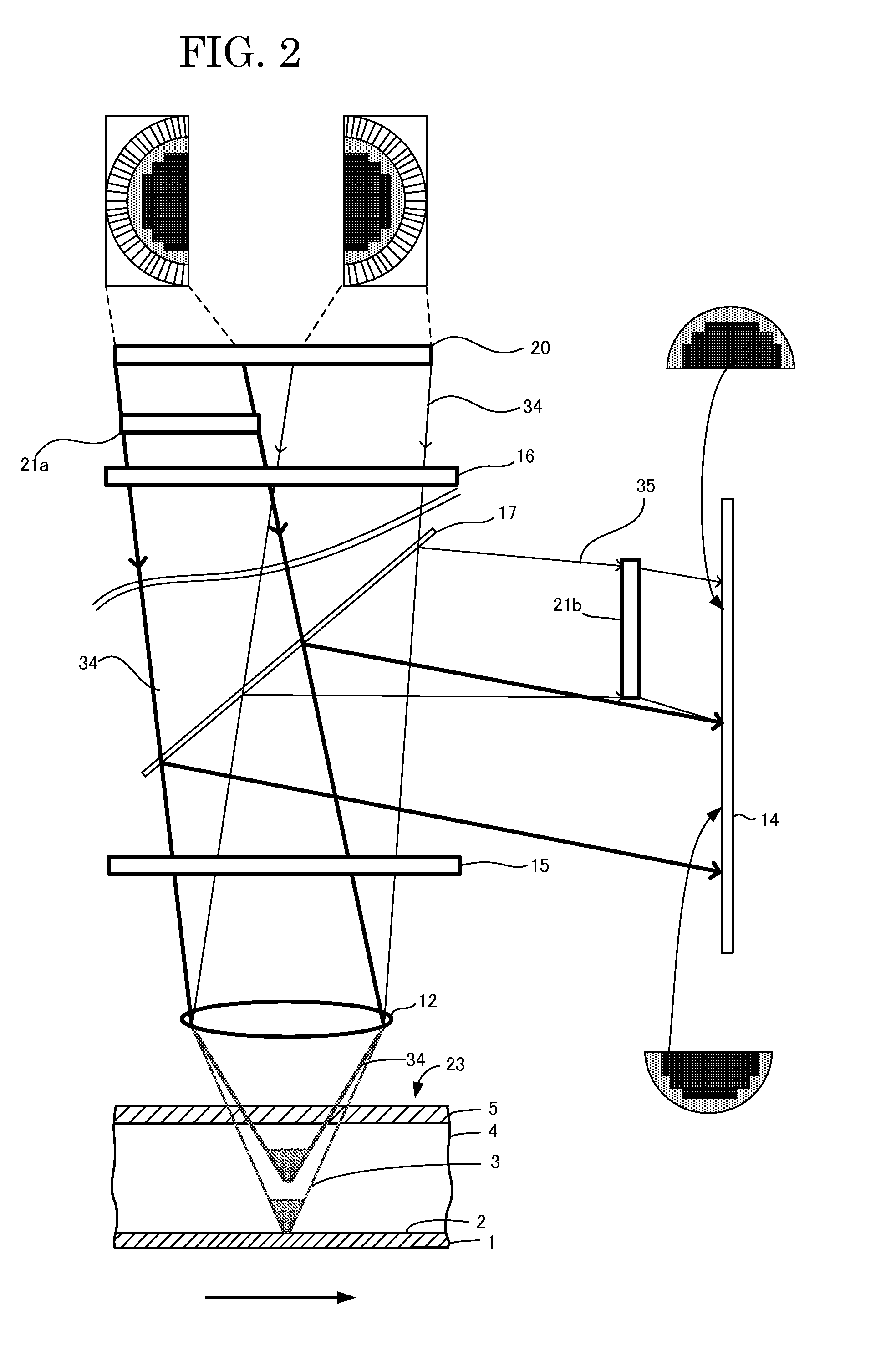
[0259] In Embodiment 2, as shown in FIG. 2, a focal point adjusting member 21a is provided between a spatial light modulator 20 that modulates a laser beam emitted from a light source and generates information beam and reference beam and the optical recording medium 23. Having a width smaller than the spatial light modulator 20, the focal point adjusting member 21a adjusts the optical path lengths of a half of the information beam and the reference beam from the spatial light modulator 20. The optical path length adjustment rate is calculated as follows: L=(n−i)×t (in which “n” is the refractive index of the focal length adjusting member, “i” is the refractive index of the air, which is one or 1, and “t” is the thi...


PUM

PropertyMeasurementUnit
optical path lengthaaaaaaaaaa
wavelengthsaaaaaaaaaa
wavelengthaaaaaaaaaa

Abstract

The present invention provides an optical recording method and an optical recording apparatus for holographically recording information allowing for reductions in uneven consumption of the material through the thickness of a recording layer during recording to achieve high density recording and an increased recording capacity, an optical recording medium, and an optical reproducing method and an optical reproducing apparatus using the optical recording method. The optical recording method includes irradiating the optical recording medium with an information beam and a reference beam, dividing at least one of the information beam and the reference beam into two or more between a light source thereof and an optical recording medium, and adjusting the optical path lengths of the divided information beams and reference beams so that they focus on points different from each other through the thickness of the recording layer.

Description

BACKGROUND OF THE INVENTION [0001] 1. Field of the Invention [0002] The present invention relates to an optical recording method and an optical recording apparatus for holographically recording information in which uneven consumption of the material through the thickness of a recording layer during recording is reduced so as to achieve high density recording and high multiple recording, an optical recording medium for recording by the optical recording method so that information recorded in a large volume and at high density is reproduced with efficiency, and an optical reproducing method and an optical reproducing apparatus for reproducing information recorded by the optical recording method in an efficient and excellent manner. [0003] 2. Description of the Related Art [0004] Optical recording methods for holographically recording information on optical recording media generally utilize interference of an information beam (an object beam) carrying image information with reference b...

Claims


Application Information

Patent Timeline
Patent Type & Authority Applications(United States)
IPC IPC(8): G11B7/00
CPCG03H1/04G03H1/0465G03H2223/17G11B7/0065G03H1/041G11B7/1365G11B7/24044G11B7/245G11B7/266G11B7/083
Inventor USAMI, YOSHIHISAMASUKANE, KAZUYUKI
Owner FUJIFILM CORP
Why Eureka
Try Eureka