Intravascular Flow Modifier And Reinforcement Device And Deployment System For Same

a technology of which is applied in the field of intravascular flow modifier and reinforcement device, can solve the problems of limiting the applicability of neurovascular aneurysm repair procedures, affecting the stability of the device, so as to promote a non-turbulent flow pattern, enhance the flexibility of the device, and cover and reinforce large neck aneurysms.

Inactive Publication Date: 2008-01-24
DEPUY SYNTHES PROD INC
View PDF43 Cites 63 Cited by
  • Summary
  • Abstract
  • Description
  • Claims
  • Application Information

AI Technical Summary

Benefits of technology

[0019] The devices, systems and methods of the present invention provide important advantages over prior art devices in that they eliminate the necessity for balloon or mechanical placement of devices which can cause unnecessary trauma to the delicate vasculature which has already been damaged by the presence of the aneurysm. The invention additionally provides a flexible device which promotes a non-turbulent flow pattern. For these reasons, the invention is particularly useful to cover and reinforce large neck aneurysms. The presence and design of the alternating zigzag bends enhances the flexibility of the device and enhances the ability of the stent to be flattened and compressed, and to subsequently deploy the stent within the vasculature, an issue of considerable importance if neither balloon nor mechanical placement methods are to be used. The use of a helical pattern increases the structural integrity of the stent and provides sufficient radial support for weakened arterial walls when the stent is in a deployed state.
[0020] The present invention also contains numerous advantages over the prior art, including enhanced flexibility and loop strength. These characteristics are controlled by several factors including the diameter of the helical winds, the axial spacing of the winds, the diameter or thickness of the wire or hypo tubing and the angle of the alternating zigzag bend pattern.
[0021] The collapsibility of the stent for deployment purposes is a function of material and stent configuration. The use of superelastic and / or shape-memory material in combination with the unique helical pattern allows for the stent to be compressed or flattened and stretched for placement within a sheath or catheter. Thus, the invention provides a wide variety of performance characteristics that can be designed as part of the stent configuration.

Problems solved by technology

For example, when the defect is located in the brain, a great deal of difficulty is involved in treatment of small defects in the blood vessels with conventional surgical techniques.
One aspect of these surgical treatments is that an aneurysm or other malformation is symptomatic of a general weakening of the vasculature in the area containing the aneurysm, and mere treatment of the aneurysm does not necessarily prevent a subsequent rupture in the surrounding area of the vessel.
While such procedures may be useful in certain aspects of vascular surgery in which vasoocclusive devices are used, the weakness of the vasculature and the tortuosity of the neurovasculature places limits on the applicability of such stents in procedures to repair neurovascular aneurysms.
Furthermore, the use of placement techniques, such as balloons or mechanical expansions of the type often found to be useful in cardiac surgery, are relatively less useful in vasoocclusive surgery, particularly when tiny vessels, such as those found in the brain, are to be treated.

Method used


Image

  • Intravascular Flow Modifier And Reinforcement Device And Deployment System For Same
  • Intravascular Flow Modifier And Reinforcement Device And Deployment System For Same
  • Intravascular Flow Modifier And Reinforcement Device And Deployment System For Same

Examples


Embodiment Construction

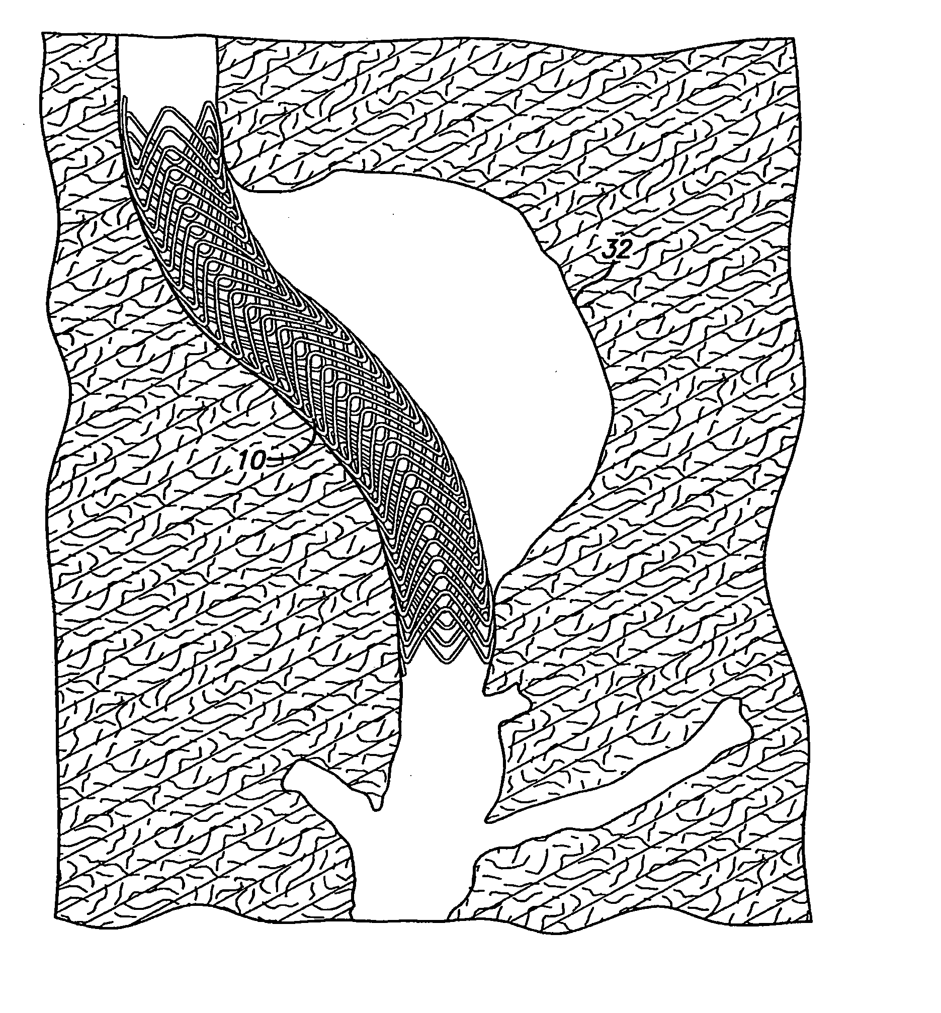
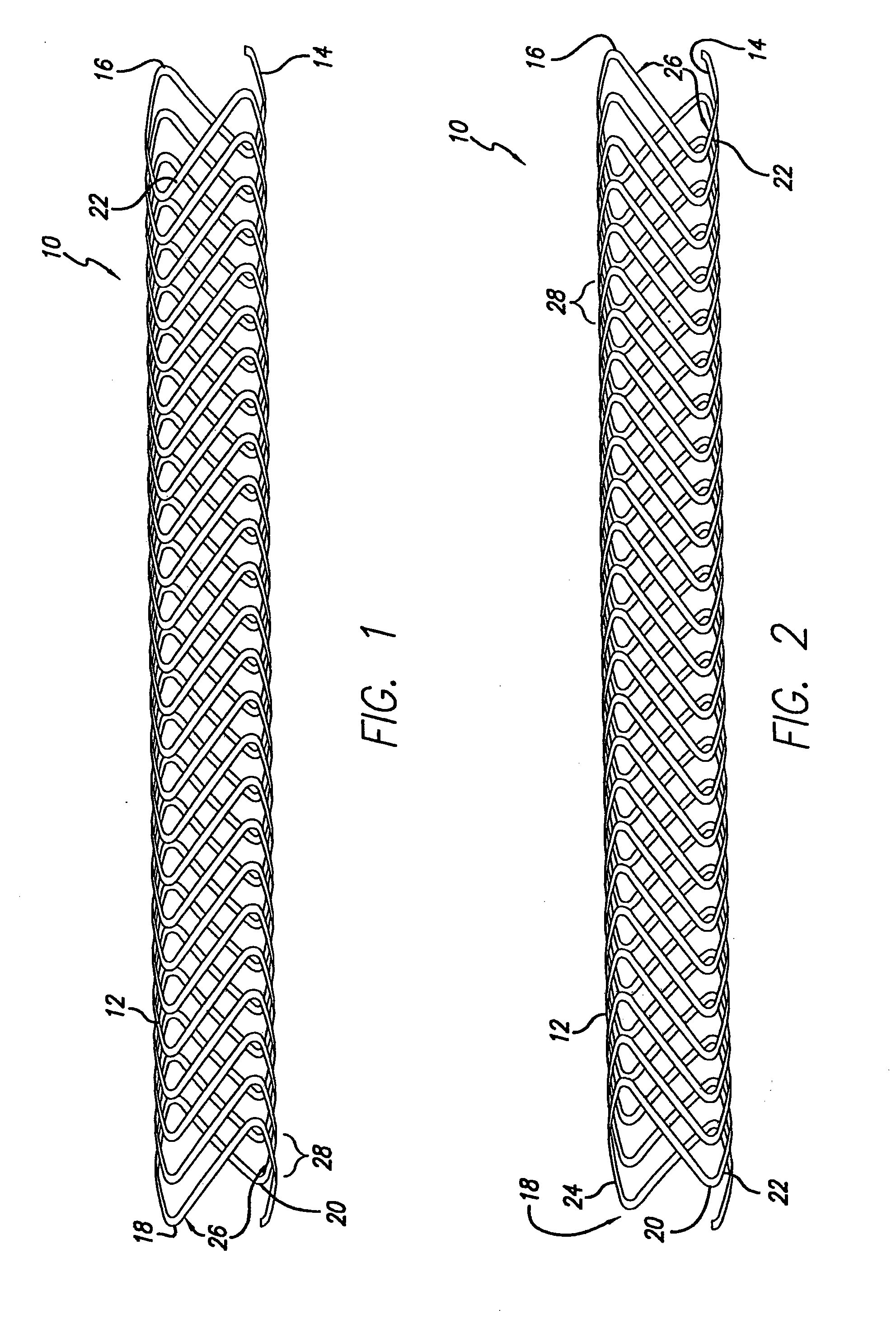
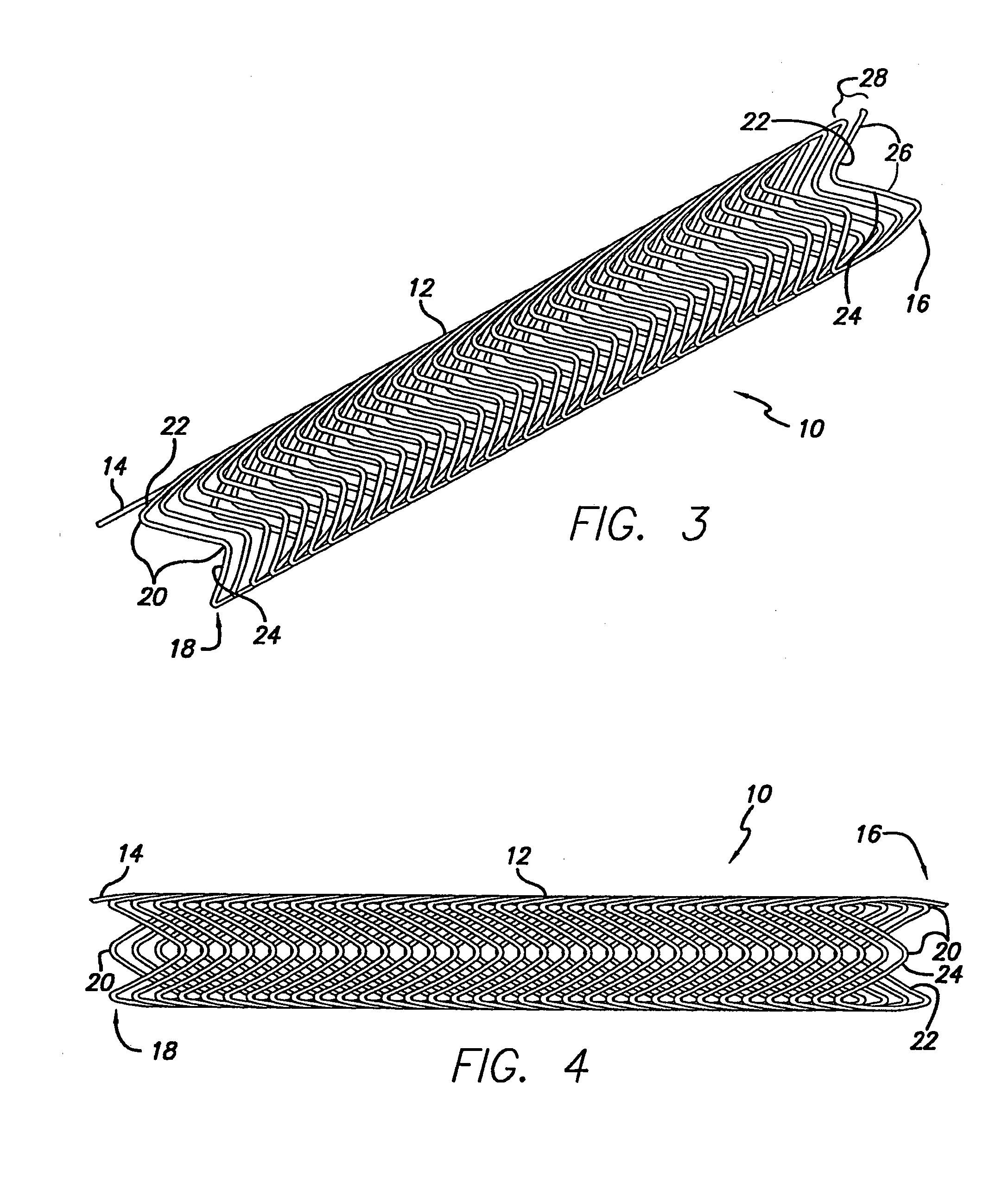
[0040] As shown in the exemplary drawings, which are provided for the purposes of illustration and not by way of limitation, the intravascular flow modifier and reinforcement device or stent of the present invention is designed to be deployed intravascularly without the necessity of balloons or other expansive elements. The intravascular device of the present invention is particularly useful for treatment of damaged arteries incorporating aneurysms and the like, particularly those which are treatable by the use of embolic coils or other embolic devices or agents used to occlude the aneurysm. More particularly, the device of the present invitation may be used to reinforce the area in the vicinity of the aneurysm while allowing placement of one or more embolic coils through the gaps in the device, while assisting in the retention of the embolic devices within the aneurysm.

[0041] In general, an intravascular flow modifier and reinforcement device or stent constructed according to the ...


PUM


Abstract

A stent includes a cylindrical frame consisting of a series of helical winds containing a pattern of alternating zigzag bends. The frame may be made of resilient wire or from a piece of laser cut hypo tubing by placing the stent over a notched portion of a pusher catheter member, and retained on the pusher catheter member by a release wire threaded through the pusher catheter member and over the stent. The stent may also be deployed by placing the stent over a pusher catheter member having opposing notched portions, and retaining the stent and pusher catheter member in a delivery catheter, which can be withdrawn when stent reaches the site to be treated to release the stent.

Description

CROSS-REFERENCES TO RELATED APPLICATION [0001] This is a divisional of U.S. Utility patent application Ser. No. 10 / 699,612 filed on Oct. 31, 2003, which claims priority to U.S. Provisional Patent Application No. 60 / 447,601, filed Feb. 14, 2003. Each of these applications is hereby incorporated by reference as if set forth in full herein.BACKGROUND OF THE INVENTION [0002] 1. Field of the Invention [0003] The present invention relates to an intravascular flow modifier and reinforcement device, i.e., a stent, for use within a body vessel, and more particularly, to a stent for use in combination with vasoocclusive devices placed adjacent to an aneurysm for the purpose of occluding the aneurysm and providing reinforcement for the area of the blood vessel in the vicinity of the aneurysm. [0004] 2. Description of Related Art [0005] The progress of the medical arts related to treatment of vascular malformations has dramatically improved with the availability of intravascular devices capable...

Claims


Application Information

Patent Timeline
Patent Type & Authority Applications(United States)
IPC IPC(8): A61F2/06A61F2/88
CPCA61F2/88A61F2/95A61F2/89A61F2220/0016
Inventor LEOPOLD, ERIC W.FRIEDMANN, JOSEF L.PADILLA, NEAL H.
Owner DEPUY SYNTHES PROD INC
Why Eureka
Try Eureka