Intra-Tracheal Sputum Aspirating Apparatus

a tracheal aspiration and sputum technology, applied in the direction of suction devices, wound drains, medical insufflators, etc., can solve the problems of inability to treat sputum in trachea with continuing artificial respiration, weak suction power of tube pumps, etc., and achieve the effect of preventing secondary infection

Inactive Publication Date: 2008-01-31
KOKEN CO LTD
View PDF7 Cites 34 Cited by
  • Summary
  • Abstract
  • Description
  • Claims
  • Application Information

AI Technical Summary

Benefits of technology

[0015] In the meanwhile, sputum formed in trachea of patient, ascends trachea among respiration and exhaust of artificial respiration apparatus and stored gradually at the top of tracheal cannula. Further, at the top of the tracheal cannula an opening for sputum aspiration is formed. Therefore, the inventors of the present invention it is realized that, even if a tube pump whose suction power is small as a sputum aspirator is used, sputum in trachea can be aspirated sufficiently, and accomplished the present invention.
[0016] The object of the present invention is to provide a sputum aspirator which can aspirate sputum in trachea continuously and safely without injuring inner surface of trachea, even if in a state that an end part of a suction tube, which is left in trachea, is contacted with inner surface of trachea.
[0017] Further, the object of the present invention is to provide a sputum aspirator that can treat sputum characterized that it does not alter inner pressure of trachea of respirator when positive pressure is loaded to lung, can treat sputum with continuing artificial respiration and can prevent secondary infection caused by infectious pathogen existing in air exhausted from a collection bottle.

Problems solved by technology

However, the conventional sputum aspirator 100 has problems mentioned below.
Said adapter for artificial respiration and aspiration has complicated valve structural feature characterized that when one valve is open another one is shut.
That is, it is impossible to treat sputum in trachea with continuing artificial respiration.
However, suction power of tube pump is weak and flow rate of liquid per unit time is small.

Method used


Image

  • Intra-Tracheal Sputum Aspirating Apparatus
  • Intra-Tracheal Sputum Aspirating Apparatus
  • Intra-Tracheal Sputum Aspirating Apparatus

Examples


example 1

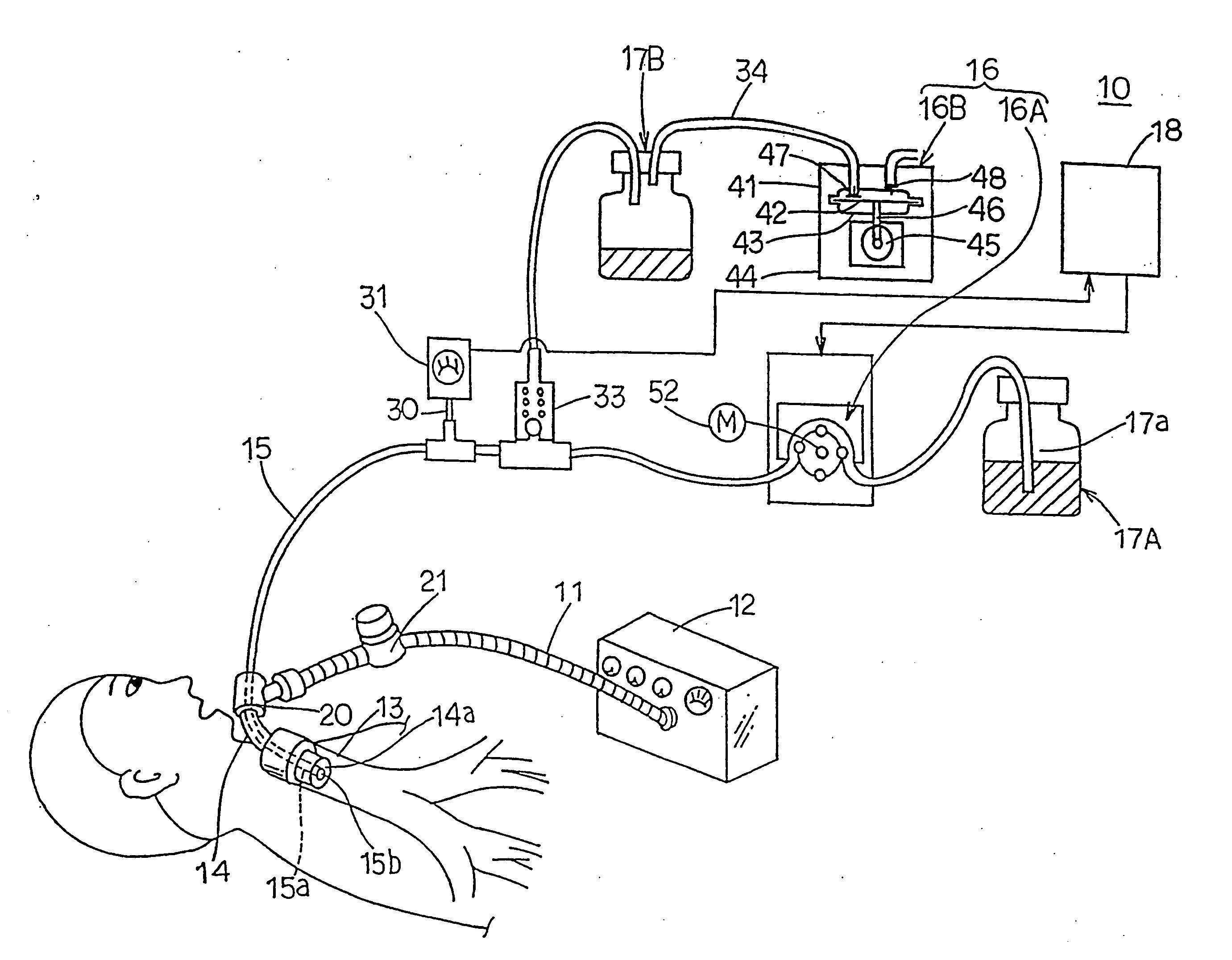
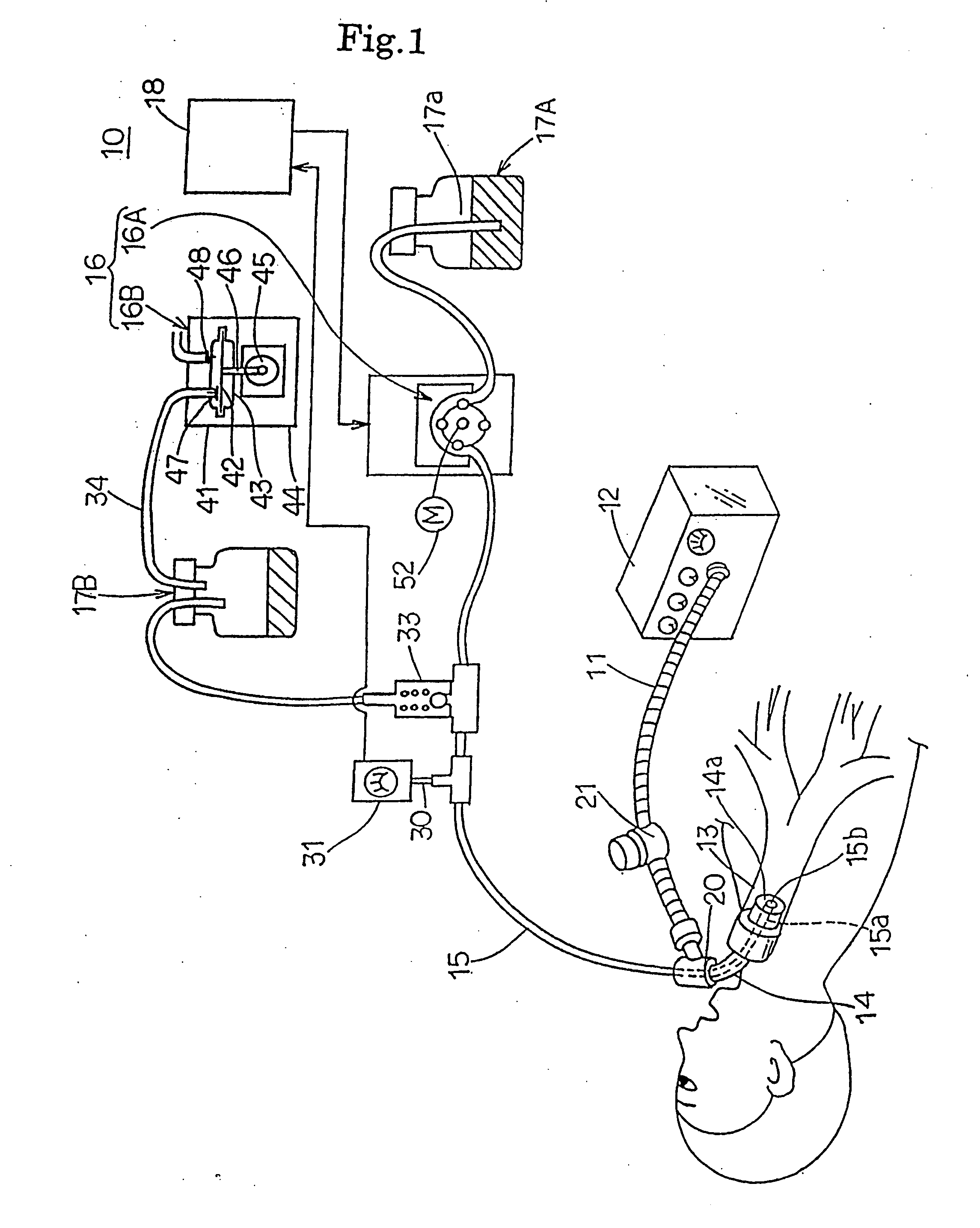
[0064] In FIG. 1, 10 indicates an artificial respiration system which uses an intra-tracheal sputum aspiration apparatus of Example 1. This artificial respiration system provides a respirator 12 to which a respiration tube 11 for air supply and for exhausting are connected, a tracheal cannula 14 connected with a respiration tube 11, which is to be inserted into trachea 13 of a patient, a sputum aspiration apparatus (intra-tracheal sputum aspiration apparatus) 16 to which a suction tube (suction catheter) 15 connected with the respiration tube 11 and to suck out sputum stored in trachea 13 is connected, two sputum collection bottles 17A and 17B and a control part 18 which controls suction pressure of sputum by the sputum aspiration apparatus 16 and controls ON-OFF of the respirator 12 by a sequencer.

[0065] The respirator 12 is a device characterized to drive an installed compressor by every certain interval so as to maintain respiration of patient. The respiration tube 11 is connect...

example 2

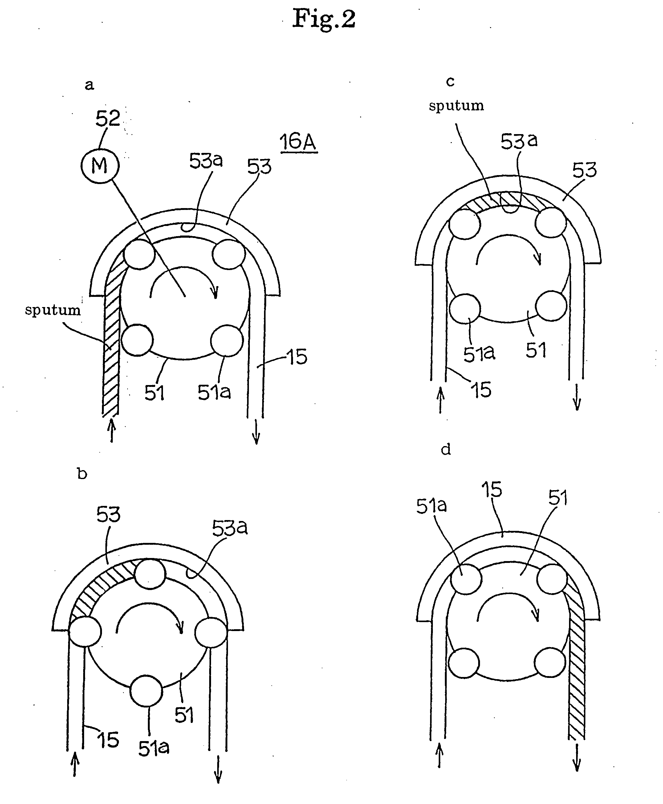
[0094] The intra-tracheal sputum aspiration apparatus of Example 2 of the present invention will be illustrated referring to FIG. 5. As shown in FIG. 5, an artificial respiration system 10A which uses the intra-tracheal sputum aspiration apparatus of Example 2 is not an example that control the suction of sputum in response to alteration of inner pressure of a suction tube 15 based on the detected signal of a pressure sensor 31 like as to Example 1, but an example to use only tube pump 16A and sucks sputum continuously by low speed, quantitatively (100 cc / sec.) and at high pressure.

[0095] Therefore, in Example 2, support pump 16B, sputum collection bottle 17B, control part 18, first branch tube 30, second branch tube 32, relief valve 33 and negative pressure tube 34 are omitted. Therefore, suction control of sputum using a pressure sensor 31 can not be carried out, but the numbers of parts of an artificial respiration system 10A are reduced and can be fabricated by lower cost.

[009...

example 3

[0097] The intra-tracheal sputum aspiration apparatus of Example 3 of the present invention will be illustrated referring to FIG. 6.

[0098] As shown in FIG. 6, an artificial respiration system 10B, which uses the intra-tracheal sputum aspiration apparatus of Example 3, is an example that control the output of a tube pump 16A in response to alteration of inner pressure of a suction tube 15 based on the detected signal of a pressure sensor 31.

[0099] Specifically, when suction pressure of sputum is ascent, it is detected by a pressure sensor 31, and a control part 18 ascends the output of the tube pump 16A. On the contrary, when suction pressure of sputum is dropped, the drop is detected by the pressure sensor 31, and the control part 18 makes drop the output of the tube pump 16A.

[0100] Accordingly, the numbers of parts of an artificial respiration system 10A are reduced compared with Example 1 and can be fabricated by lower cost maintaining the suction control of sputum using the pr...


PUM


Abstract

An intra-tracheal sputum aspiration apparatus arranged so that air feeding to and air evacuation from trachea (13) by means of artificial respirator (12) are carried out through tracheal cannula (14) and so that in the event of sputum clogging, tube pump (16A) is operated to thereby attain discharge of sputum through suction tube (15) to the outside of the body by means of a negative pressure produced thereby. By virtue of the employment of the tube pump (16A) as a sputum aspirator (16), the intra-airway pressure by the artificial respirator (12) would have substantially no fluction even when a positive pressure is applied to the lungs. Consequently, sputum disposal can be accomplished while maintaining artificial artificial respiration, so that there can be prevented any secondary infection by infectious agents discharged from sputum collection bottle (17) into the air.

Description

FIELD OF THE INVENTION [0001] The present invention relates to an intra-tracheal sputum aspiration apparatus, more in detail, relates to an automatic aspirating technique which is carried out through a hole formed in tracheal by tracheotomy operation. BACKGROUND OF THE INVENTION [0002] For the purpose to maintain respiration of a patient, a technique to carry out artificial respiration using a respirator is developed. This technique is to insert a tracheal cannula into incised trachea and to carry out artificial respiration by connecting a respiration tube, which is extended from the respirator, with the tracheal cannula through an adapter. In a case of artificial respiration, sputum accumulated in trachea shuts up respiratory tract. Therefore, treatment of accumulated sputum is a problem. [0003] As an explanatory example of a treating method of sputum, a method that a care giver removes an adaptor from a tracheal cannula, then insert a suction tube into an opening of the tracheal c...

Claims


Application Information

Patent Timeline
Patent Type & Authority Applications(United States)
IPC IPC(8): A61M16/04
CPCA61M16/0463A61M16/0484A61M16/0465A61M2016/0027A61M1/00A61M13/00A61M27/00
Inventor TOKUNAGA, SHUICHI
Owner KOKEN CO LTD
Why Eureka
Try Eureka