Plasma processing apparatus and plasma processing method

Inactive Publication Date: 2008-01-31
HITACHI HIGH-TECH CORP
View PDF6 Cites 19 Cited by
  • Summary
  • Abstract
  • Description
  • Claims
  • Application Information

AI Technical Summary

Benefits of technology

[0022]Furthermore, even when the surface roughness of the electrode surface changes with time owing to the plasma processing, the thermal conductivity at the contact zone can be minimized beca

Problems solved by technology

Therefore, the plasma processing apparatus cannot cope with a large change of the wafer temperature distribution when such a change takes place.
Because this method adjusts the wafer temperature by means of only the difference of the thermal conductivities of the heat transfer gases, the contact thermal conductivity of a contact zone at which the wafer and the electrode keep mutual contact cannot be changed with the result that the variable range of the wafer temperature is narrow.
Similarly, when the wafer temperature is adjusted by using the difference of the thermal conductivities by the kind of the heat transfer gases supplied to the two systems, respectively, t

Method used


Image

  • Plasma processing apparatus and plasma processing method
  • Plasma processing apparatus and plasma processing method
  • Plasma processing apparatus and plasma processing method

Examples


Example

Embodiment 1

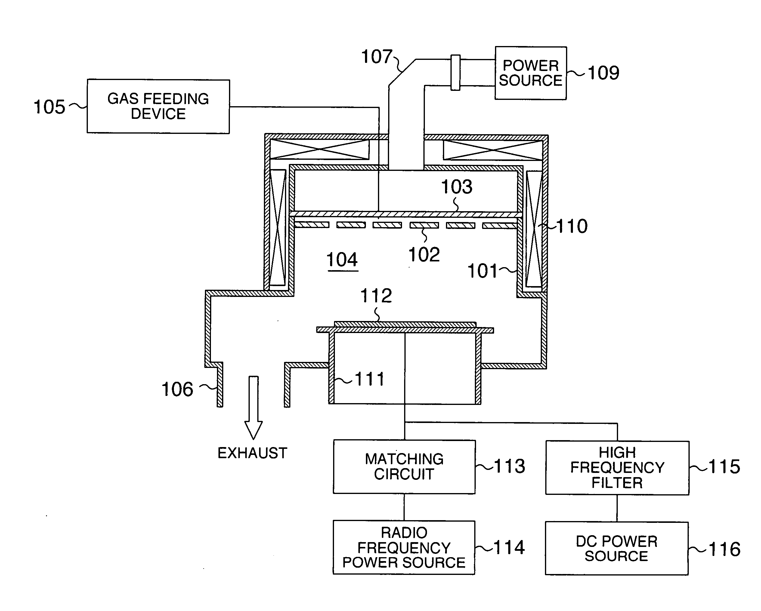
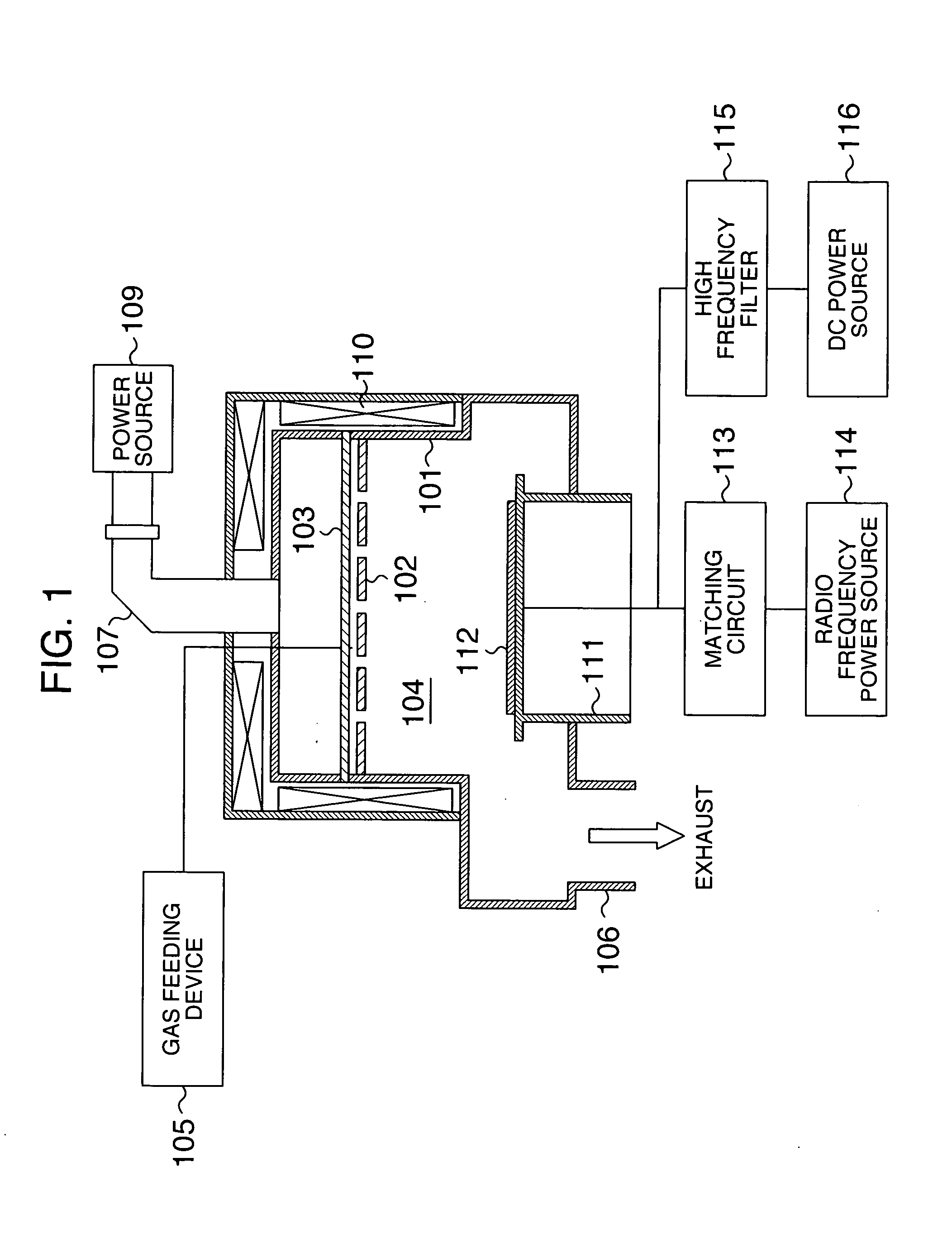
[0031]A microwave ECR (Electron Cyclotron Resonance) etching apparatus according to an embodiment of the invention will be hereinafter explained with reference to FIGS. 1 to 3. FIG. 1 is a longitudinal sectional view showing an outline of a construction of a plasma processing apparatus according to an embodiment of the invention

[0032]In the drawing, the plasma processing apparatus according to this embodiment includes a shower plate 102 (formed of quartz, for example) for introducing an etching gas into a vacuum vessel 101 and a dielectric window 103 (formed of quartz, for example) that are arranged at upper parts of the vacuum container 101 the upper part of which is open. A processing chamber 4 is formed when this vacuum vessel 101 is sealed. A gas feeding device 105 for causing the etching gas to flow is connected to the shower plate 102. A vacuum exhaust device (not shown in the drawing) is connected to the vacuum vessel 101 through a vacuum exhaust port 106.

[0033]A ...

Example

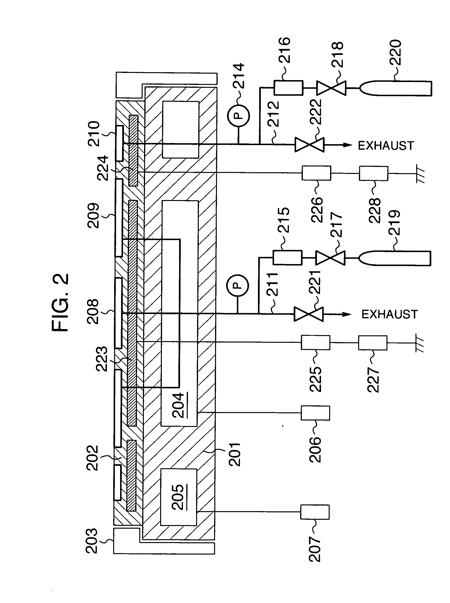
[0061]The second embodiment of the invention will be explained with reference to FIG. 5. FIG. 5 is a longitudinal sectional view showing an outline of a construction of a wafer holding electrode of a plasma processing apparatus according to this embodiment. The difference of this drawing from Embodiment 1 will be explained. FIG. 5 shows a wafer holding electrode according to this embodiment of the invention. The wafer holding electrode 111 (hereinafter called “electrode”) used for the plasma processing apparatus of this embodiment includes a substrate 501 as an electrode structure, a flame coating film 502 of alumina and a temperature controller (not shown) for the substrate 501.

[0062]A plurality of independent heat transfer grooves 503 for supplying a heat transfer gas is formed on the electrode surface between a wafer 112 and the flame coating film 502. A piping arrangement 504 for supplying the heat transfer gas, a pressure gauge 505 for measuring the pressure between the wafer 1...


PUM

PropertyMeasurementUnit
Temperatureaaaaaaaaaa
Bias potentialaaaaaaaaaa
Pressureaaaaaaaaaa

Abstract

The invention relates to a plasma processing apparatus and a plasma processing method and particularly relates to a plasma processing apparatus suitable for executing an etching processing of a work by using plasma.

Description

BACKGROUND OF THE INVENTION[0001]This invention relates to a plasma processing apparatus and a plasma processing method. More particularly, the invention relates to a plasma processing apparatus that is suitable for conducting or subjecting a work or material to be processed to an etching processing by using plasma.[0002]Dry etching using plasma has generally been executed in semiconductor fabrication processes. Various systems have been employed for plasma processing apparatuses for executing dry etching.[0003]Generally, a plasma processing apparatus includes a vacuum processing chamber, a gas feeder connected to the vacuum processing chamber, a vacuum exhaust system for keeping an internal pressure of the vacuum processing chamber at a desired value, an electrode for supporting a wafer substrate and a plasma generation unit for generating plasma inside the vacuum processing chamber. When a processing gas supplied from a shower plate, etc, into the vacuum processing chamber is brou...

Claims


Application Information

Patent Timeline
IPC IPC(8): H01L21/306C23F1/00C23C16/00
CPCH01L21/6833H01J2237/2001H01L21/3065
Inventor YASUI, NAOKIKITADA, HIROHO
Owner HITACHI HIGH-TECH CORP
Why Eureka
Try Eureka