Method and apparatus for operating electrical machines

a technology of electrical machines and methods, applied in the direction of electric generator control, motor/generator/converter stopper, dynamo-electric converter control, etc., can solve the problems of known capacitors not having a sufficient response time characteristic, and the effect of insulating to breakdown

Inactive Publication Date: 2008-01-31
GENERAL ELECTRIC CO
View PDF39 Cites 18 Cited by
  • Summary
  • Abstract
  • Description
  • Claims
  • Application Information

AI Technical Summary

Benefits of technology

[0004]In one aspect, a method of operating an electrical machine is provided. The method includes providing a brushless excitation system including at least one rectifier having at least one diode. The method also includes providing at least one voltage amplitude limiter assembly including at least one resistor and at least one transient voltage suppressor (TVS) electrically coupled with the at least one resistor to form at least one voltage suppression unit. The method further includes transmitting an electrical signal having a current and a voltage to each voltage suppression unit, the voltage having an amplitude. The method also includes electrically coupling the at least one voltage amplitude limiter assembly to the at least one diode. The method further includes transmitting the electrical signal through the rectifier and the voltage suppression unit such that voltage amplitude excursions of the electrical signal are facilitated to be reduced.
[0006]In a further aspect, a brushless excitation system for an electrical machine is provided. The electrical machine has an excitation field apparatus. The system includes an electrical power source and a diode rectifier electrically coupled to the electrical power source and the excitation field apparatus. The system also includes a voltage amplitude limiter assembly electrically coupled to the diode rectifier. The assembly includes at least one resistor and at least one transient voltage suppressor (TVS) electrically coupled to the at least one resistor to form at least one voltage suppression unit. The voltage suppression unit is configured to reduce a voltage amplitude excursion of an electrical signal received that exceeds a predetermined voltage amplitude.

Problems solved by technology

Over time, continued exposure to voltage spikes may cause the insulation to breakdown.
However, known capacitors may not have a sufficient response time characteristics and / or may be of such mass and size as to inhibit the operation of the diode wheel.

Method used


Image

  • Method and apparatus for operating electrical machines
  • Method and apparatus for operating electrical machines
  • Method and apparatus for operating electrical machines

Examples


Embodiment Construction

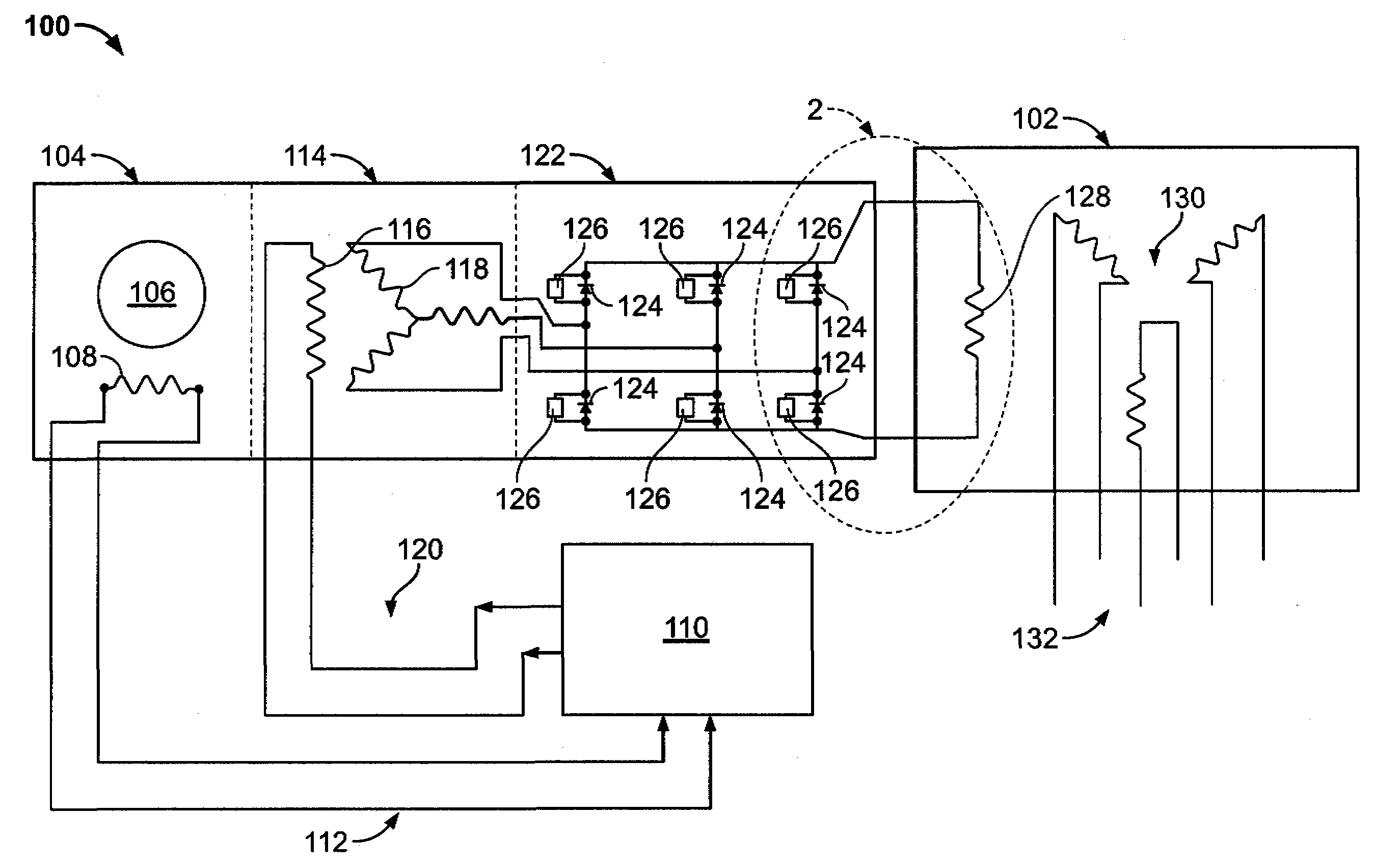
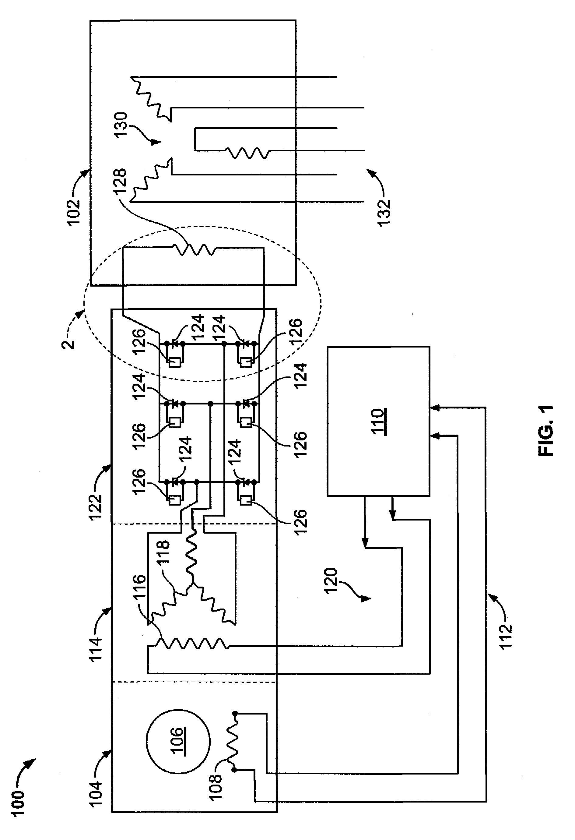
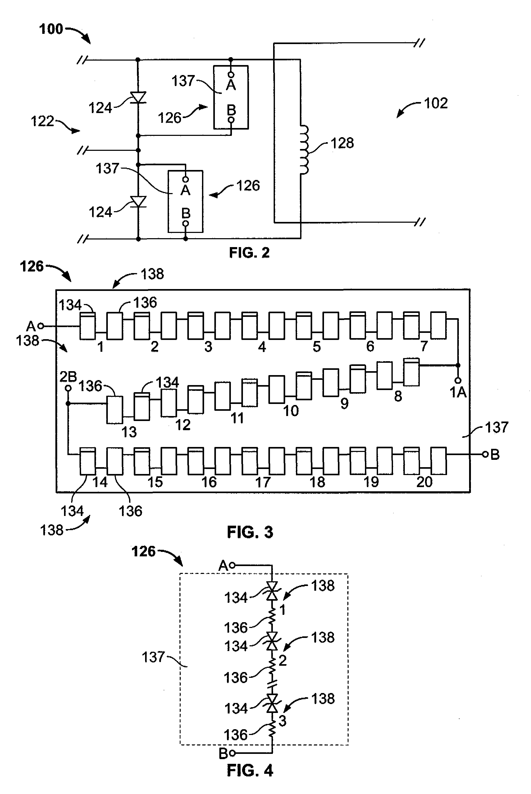
[0011]FIG. 1 is a schematic view of an exemplary generator brushless excitation system 100 that is used to provide excitation power to an electric machine 102. FIG. 2 is an enlarged schematic view of a portion of system 100. In the exemplary embodiment, and hereinafter, electric machine 102 is a three-phase electric power generator 102. Alternatively, electric machine 102 is an electrically-driven motor (not shown in FIG. 1) that includes a brushless excitation scheme. An electric power source 104 generates and transmits electric power for use within system 100. In the exemplary embodiment, power source 104 is a permanent magnet generator (PMG) that generates electrical alternating current (AC) power for use within system 100. Alternatively, system 100 is a static excitation system that includes a power source that is any electric power delivery apparatus that enables system 100 to function as described herein, including but not limited to, batteries. PMG 104 includes a rotor 106 an...


PUM


Abstract

A method and associated apparatus for operating an electrical machine includes providing a brushless excitation system including at least one rectifier having at least one diode. The method also includes providing at least one voltage amplitude limiter assembly including at least one resistor and at least one transient voltage suppressor (TVS) electrically coupled with the at least one resistor to form at least one voltage suppression unit. The method further includes transmitting an electrical signal having a current and a voltage to each voltage suppression unit, the voltage having an amplitude. The method also includes electrically coupling the at least one voltage amplitude limiter assembly to the at least one diode. The method further includes transmitting the electrical signal through the rectifier and the voltage suppression unit such that voltage amplitude excursions of the electrical signal are facilitated to be reduced.

Description

BACKGROUND OF THE INVENTION[0001]This invention relates generally to electrical machines and more particularly, to methods and apparatus for operating electrical machines.[0002]At least some known electric power generators include a stator and a rotor coupled to an external excitation system that, in some configurations, includes a brushless exciter that includes a rotating armature and a diode rectifier. Specifically, at last some brushless exciters are electrically connected to a generator field winding coupled to the generator rotor. The rotating armature and diode rectifier are sometimes rotatably coupled to the generator rotor is a configuration in which the diode rectifier is configured as a diode wheel and wherein the rotating armature, the diode wheel, and the generator rotor are electrically connected. An alternating current (AC) signal generated within the rotating armature is transmitted to the diode wheel wherein the AC current signal is rectified to a direct current (DC...

Claims


Application Information

Patent Timeline
Patent Type & Authority Applications(United States)
IPC IPC(8): H02H7/09
CPCH02P9/102H02P2101/15H02P9/302
Inventor FISH, WILLIAM E.
Owner GENERAL ELECTRIC CO
Why Eureka
Try Eureka