Syngas Power Systems and Method for Use Thereof

a power system and power technology, applied in the direction of machinery/engines, mechanical equipment, chemistry equipment and processes, etc., can solve the problems of high cost, high complexity of typical decarbonisation plant, and economic penalties for the emission of various materials to the environmen

Active Publication Date: 2008-02-07
AIR PROD & CHEM INC
View PDF14 Cites 25 Cited by
  • Summary
  • Abstract
  • Description
  • Claims
  • Application Information

AI Technical Summary

Problems solved by technology

In many industrialized nations, power plants are subject to, or will become subject to, economic penalties for emission of various materials to the environment.
A typical decarbonisation plant is highly complex as it involves many catalytic reactors such as a desulphurization reactor, pre-reformer, auto-thermal reformer and water-gas-shift reactor.
Furthermore, the process is currently thermodynamically inefficient and costly.
For example, a typical decarbonisation process often results in an 8-12% penalty in the ...

Method used


Image

  • Syngas Power Systems and Method for Use Thereof
  • Syngas Power Systems and Method for Use Thereof
  • Syngas Power Systems and Method for Use Thereof

Examples


Embodiment Construction

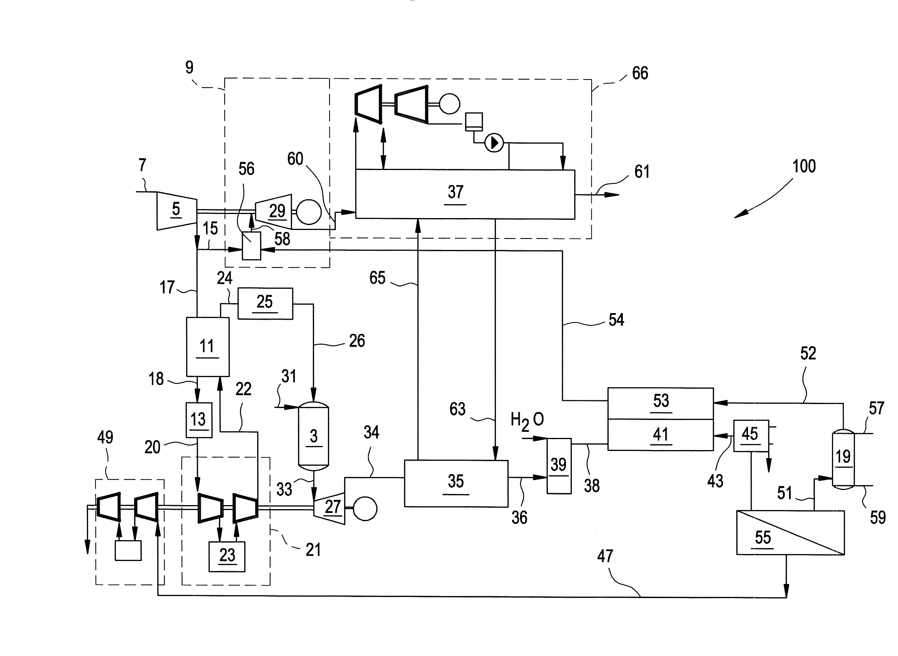
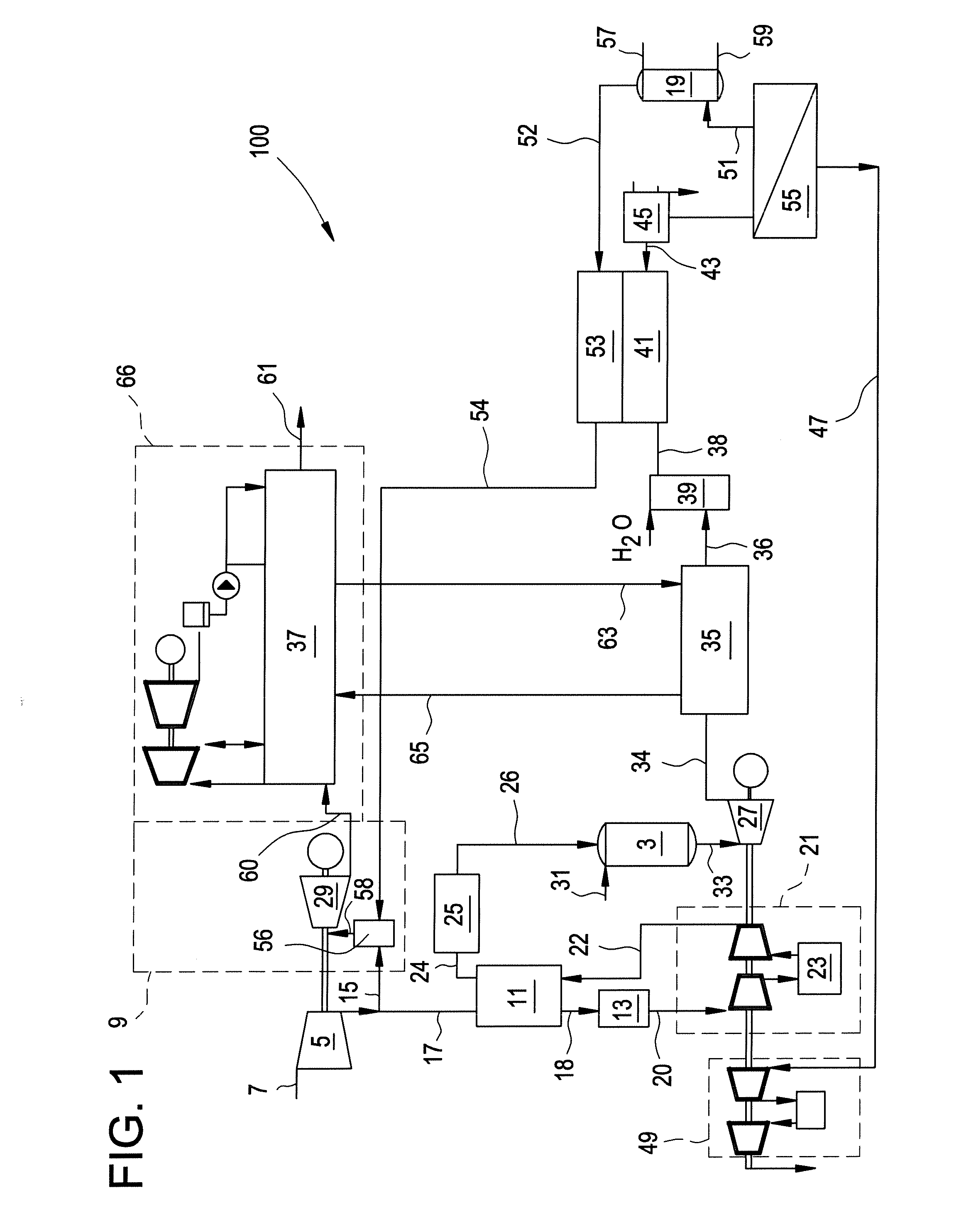
[0014]A system that recovers high temperature heat released from a reforming process comprises a high temperature syngas expander (e.g., a syngas turbo-expander) in direct flow communication with a reformer unit. This direct flow enables the efficient use of high temperature heat from the reformer directly in the expander. In addition, the system can utilize low temperature heat in saturator (also known as “humidification tower” and “humidifier”) to saturate a separated hydrogen stream, recovering the low temperature heat from trim cooler(s), intercooler(s), and / or condenser(s). The system recovers heat at various points to use the heat and attain an improvement in system electrical efficiency.

[0015]In one exemplary embodiment, FIG. 1 illustrates a Gas Turbine Combined Cycle power system 100 comprising an ambient air stream 7 (e.g., an oxygen containing stream), which enters combined cycle 100 through compressor 5, is compressed from ambient conditions to a pressure of about 10 to a...


PUM


Abstract

In one embodiment, a power system comprises: a first compressor unit, a syngas generator in fluid communication with a fuel stream and the first compressor unit, a syngas expander unit configured to directly receive the first syngas stream from the syngas generator, a first steam generator, a water gas shift reactor, and a carbon dioxide removal unit. The first compressor unit is configured to compress an air stream and form a first pressurized stream, while the syngas generator is configured to generate a first syngas stream. The syngas expander is configured to reduce the pressure of the first syngas stream. The first steam generator is configured to cool the second syngas stream. The carbon dioxide removal unit configured to remove carbon dioxide from the converted syngas stream.

Description

BACKGROUND[0001]This disclosure relates to a system and process of generating synthesis gas in a gas turbine combined cycle.[0002]In many industrialized nations, power plants are subject to, or will become subject to, economic penalties for emission of various materials to the environment. For example, controls on carbon dioxide emissions results in emissions trading and taxes, and requires permits. As the cost of emission penalties increase, measures to curb emissions are continually sought, either as a retrofit to existing plants to reduce emissions and / or as a design of new carbon dioxide (CO2)-lean power plants to lower overall emissions.[0003]One CO2 capture method is a fuel decarbonisation process, also known as a pre-combustion capture pathway. The process converts hydrocarbon (HC) fuels to a hydrogen-based fuel and carbon monoxide (e.g., synthesis gas or “syngas”). The carbon monoxide (CO) is then converted to carbon dioxide, which is removed from the system before the combu...

Claims


Application Information

Patent Timeline
IPC IPC(8): F02C6/18
CPCC01B3/34Y02E20/16C01B2203/0244C01B2203/025C01B2203/0283C01B2203/0288C01B2203/0294C01B2203/0405C01B2203/046C01B2203/0475C01B2203/06C01B2203/0894C01B2203/1241F02C3/20F02C3/22F02C6/18F02C9/40C01B2203/0238
Inventor BARTLETT, MICHAEL
Owner AIR PROD & CHEM INC
Why Eureka
Try Eureka