Angular rate sensor

a technology of angular rate sensor and gyroscope, which is applied in the direction of acceleration measurement using interia force, instruments, devices using electric/magnetic means, etc. it can solve the problems of electric symmetry broken, electric charge generated, and inherent performance limitation of angular rate sensors of this type, so as to achieve high reliability, high sensitivity, and high stability.

Active Publication Date: 2008-02-07
DENSO CORP
View PDF3 Cites 31 Cited by
  • Summary
  • Abstract
  • Description
  • Claims
  • Application Information

AI Technical Summary

Benefits of technology

[0034] The present invention has been made in consideration of the above situation in the prior art, and has as its object to provide an angular rate sensor comprising a semiconductor substrate and a piezoelectric film accumulated on the semiconductor substrate and having features such as compactness, high sensitivity, high reliability, high stability, high precision, and high mass-production capability by suppressing an electric polarization in the perpendicular direction to the piezoelectric film.

Problems solved by technology

Angular rate sensors of this type suffer from an inherent performance limitation.
However, if a stress is applied to the silicon oxide (SiO2) single crystalline piezoelectric material, the electric symmetry is broken and electric charge is generated.
Although a single crystalline tuning folk oscillator is cut from a piezoelectric material is optimized in a view of the polarities on which the sensitivity of the sensor depends, it is not easy to obtain the high sensitivity of both directions corresponding to the oscillatory direction of the tuning folk and the direction of the deformation due to the Coriolis force.
Furthermore, the pair of arms and the root member being components of the tuning folks are susceptible to external shock and external vibrations that occur at frequencies close to the arm vibrating frequency.
Such disturbances may influence the vibrating structure and produce erroneous results.
However, if an attempt of detecting the magnitude of the Coriolis force by averaging over a spatial distribution of the vibration of each particle composing the elastic material is made, it would not be effective because the Coriolis force acting on each particle cancel one another.
Therefore, secondary SAWs will never be obtained due to the cancellation.
However, even though the above mentioned single crystal piezoelectric materials such as lithium niobate (LiNbO3), lithium tantalite (LiTaO3), lithium tetraborate (Li2B4O7) are widely used for mechanical filters utilizing surface acoustic wave, it is not the best way to reduce the size of the device.
However one disadvantage of the arrangement comes from the fact that high sensitivity of the angular rate sensor which needs a lot of individual metallic dots J1, and the relative positions of the metallic dots J1 need to be fine tuned so that every metallic dot is positioned at loops of the secondary SAW caused by the Coriolis force.
Is not suitable for reducing the size of the angular rate sensor and integrating an angular rate sensor and a driving circuit thereof into one integrated device.
However, small and light weight metallic dots J1 can not bring the angular rate sensor into having high sensitivity, because the Coriolis force is proportional to both mass and rotational rate.
However, the angular rate sensor of the type shown in FIG. 41 is not effective for following reasons.
Then, achievement of high sensitivity of the angular rate sensor is difficult in the structure of the angular rate sensor of the type which is organized in such a way that the piezoelectric film J22 and the metallic dots J23 are accumulated on the semiconductor substrate J20.

Method used


Image

  • Angular rate sensor
  • Angular rate sensor
  • Angular rate sensor

Examples


first embodiment

Modification of First Embodiment

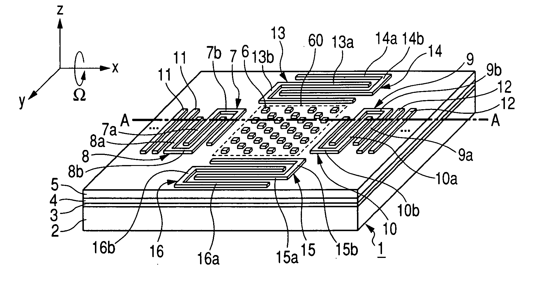
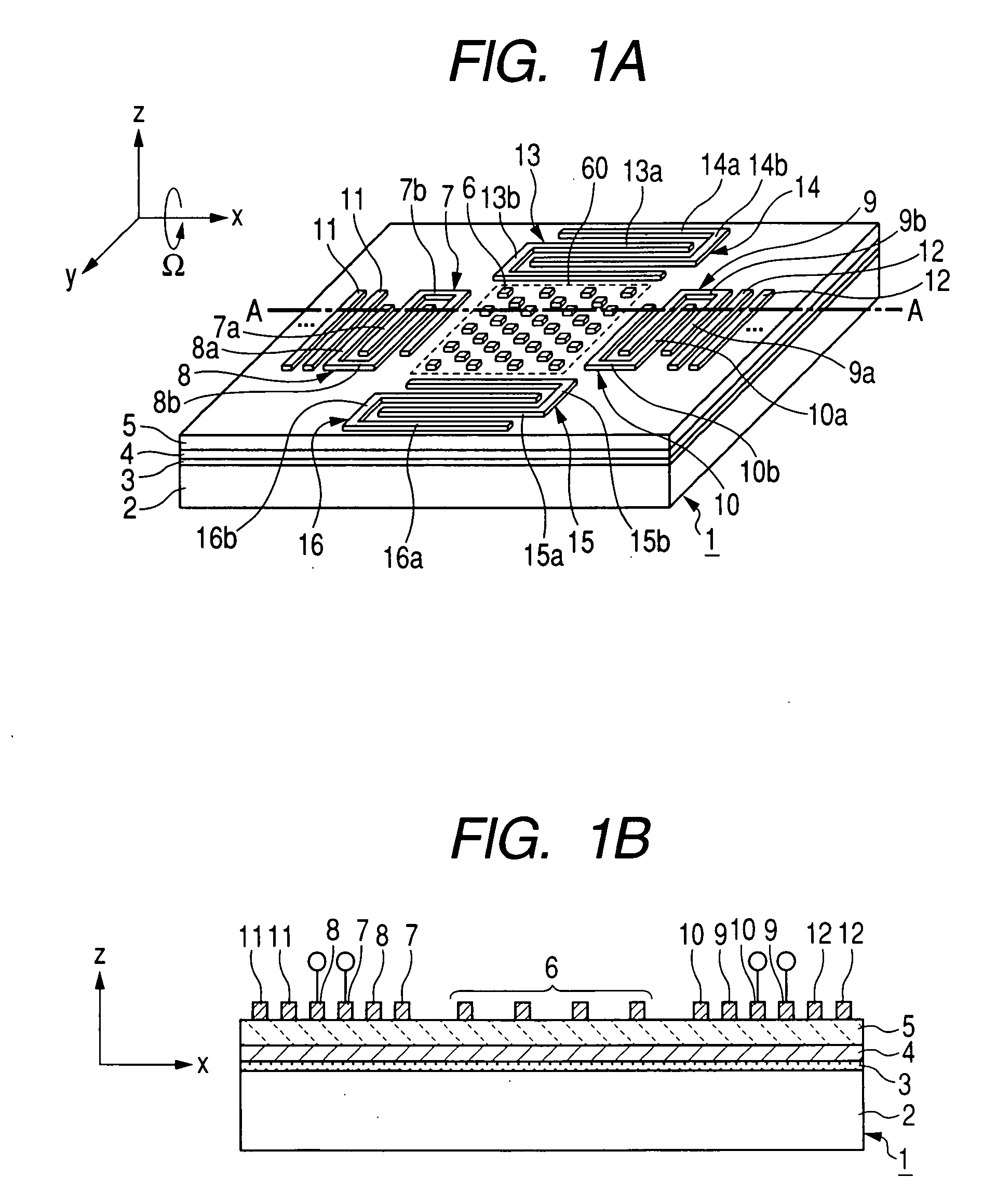
[0196]FIG. 6 shows a cross-sectional view of the angular rate sensor 1 according to the modification of the first embodiment taken along line A-A in FIG. 1A.

[0197] In the first embodiment described above in which the perturbation masses 6, the driving electrodes 7-10, the reflectors 11, 12, and the detecting electrodes 13-16 are disposed directly on the upper surface of the piezoelectric film 5, if necessary, an thin insulator film 20 is formed and inserted between the upper surface of the piezoelectric film 5 and the perturbation masses 6, the driving electrodes 7-10, the reflectors 11, 12, and the detecting electrodes 13-16. In this configuration, the perturbation masses 6, the driving electrodes 7-10, the reflectors 11, 12, and the detecting electrodes 13-16 are disposed on the thin insulator film 20. It is especially preferable in a case where the piezoelectric film 5 is made of AlN that the thin insulator film 20 is formed on the supper surface ...

second embodiment

Modification of Second Embodiment

[0215] In the second embodiment described above in which the second electrode 30, the driving electrodes 7-10, the reflectors 11, 12, and the detecting electrodes 13-16 are disposed directly on the upper surface of the piezoelectric film 5.

[0216] As shown in FIG. 11, if necessary, a thin insulator film 20 is formed and inserted between the upper surface of the piezoelectric film 5. Consequently, the second electrode 30, the driving electrodes 7-10, the reflectors 11, 12, and the detecting electrodes 13-16 are formed on the thin insulator film 20. In this configuration, the second electrode 30, the driving electrodes 7-10, the reflectors 11, 12, and the detecting electrodes 13-16 are disposed on the thin insulator film 20. In this configuration, it is possible to prevent etching the piezoelectric film 5 while the thin film of metal or conductive metallic alloy is patterned to form the second electrode 30, the perturbation masses 6, and the driving el...

third embodiment

Modification of Third Embodiment

[0233] In the third embodiment described above in which the second electrode 30, the driving electrodes 7-10, the reflectors 11, 12, and the detecting electrodes 13-16 are disposed directly on the upper surface of the piezoelectric film 5.

[0234] As shown in FIG. 16, if necessary, a thin insulator film 20 is formed and inserted between the upper surface of the piezoelectric film 5. Consequently, the second electrode 30, the driving electrodes 7-10, the reflectors 11, 12, and the detecting electrodes 13-16 are formed on the thin insulator film 20. In this configuration, the second electrode 30, the driving electrodes 7-10, the reflectors11, 12, and the detecting electrodes 13-16 are disposed on the thin insulator film 20. In this configuration, the contact holes 5a penetrate the thin insulator film 20 so as to electrically connect the first electrode 4 to the second electrode 30.


PUM


Abstract

An angular rate sensor comprises a piezoelectric film having a first and a second surfaces forming an x-y plane and utilizes a perturbation mass coherently vibrating elastic acoustic waves on which a Coriolis force acts when the angular rate sensor undergoes a rotary motion about an x-direction. A first elastic acoustic wave is excited in the piezoelectric film by a driving transducer and a second elastic acoustic wave generated by the Coriolis force proportional to an angular rate of the rotary motion of the angular rate sensor itself is detected by the detecting transducer. The angular rate sensor further comprises at least a first electrode disposed on the first surface of the piezoelectric film for discharging a surface charge caused due to piezoelectric effect at the lower surface of the film in which the first elastic acoustic wave is excited.

Description

CROSS REFERENCE TO RELATED APPLICATION [0001] The present application relates to and incorporates by references Japanese Patent Application Nos. 2006-202400 filed on Jul. 25, 2006, 2006-202399 filed on Jul. 25, 2006, and 2006-202401 filed on Jul. 25, 2006. BACKGROUND OF THE INVENTION [0002] 1. The Field of the Invention [0003] The present invention relates to angular rate sensors or gyroscopes, and more particularly to angular rate sensors configured to measure the rate of an angular rotation in a method for detecting a magnitude of a Coriolis force generated by interactions between a vibrating motion of a mass on a piezoelectric substrate and a rotary motion of the piezoelectric substrate by converting the Coriolis force into a voltage due to a piezoelectric effect. [0004] 2. Description of the Prior Art [0005] There has been increasing demand for requiring angular rate information, which is also sometimes called angular velocity information not only in the field of automotive prod...

Claims


Application Information

Patent Timeline
Patent Type & Authority Applications(United States)
IPC IPC(8): G01C19/00G01C19/5698
CPCG01C19/5698
Inventor KANO, KAZUHIKOTESHIGAHARA, AKIHIKOARAKAWA, KAZUKIASAMI, KAZUSHI
Owner DENSO CORP
Why Eureka
Try Eureka