Field emission electron gun and electron beam applied device using the same

an electron beam and electron beam technology, applied in the field of field emission electron beam and electron beam applied device, can solve the problems achieve the effects of reducing the resolution of the electron microscope, broadening the energy distribution of the emitted electrons, and sufficient image contras

Inactive Publication Date: 2008-02-07
HITACHI LTD
View PDF8 Cites 17 Cited by
  • Summary
  • Abstract
  • Description
  • Claims
  • Application Information

AI Technical Summary

Benefits of technology

[0003]When an electron source is mounted on an electron microscope, the optical axis of an electron beam is adjusted by mechanically tilting the electron source within a certain range, so that the electron beam emitted from the electron source passes through a plurality of holes, such as diaphragms, and sample current reaching to a sample becomes maximum. When the luminance of the central portion of the pattern of electron beams is low, and a high-luminance pattern is shifted from the pattern center over a mechanically adjustable range of the electron source, in order to secure the sample current required to obtain a sufficient image contrast, the total current emitted from the electron source must be increased unnecessarily. By this, a problem occurs, such as, in that the resolution of an electron microscope is reduced due to increase of the influence of Boersh effect of the emitted electrons and broadening of energy distribution of the emitted electrons.

Problems solved by technology

By this, a problem occurs, such as, in that the resolution of an electron microscope is reduced due to increase of the influence of Boersh effect of the emitted electrons and broadening of energy distribution of the emitted electrons.

Method used


Image

  • Field emission electron gun and electron beam applied device using the same
  • Field emission electron gun and electron beam applied device using the same
  • Field emission electron gun and electron beam applied device using the same

Examples


example 1

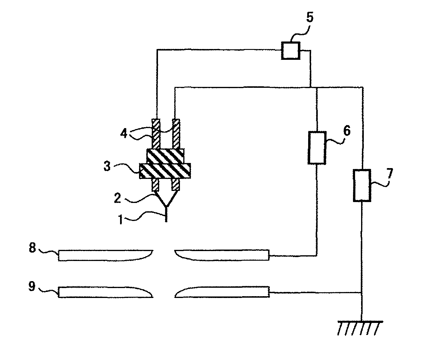
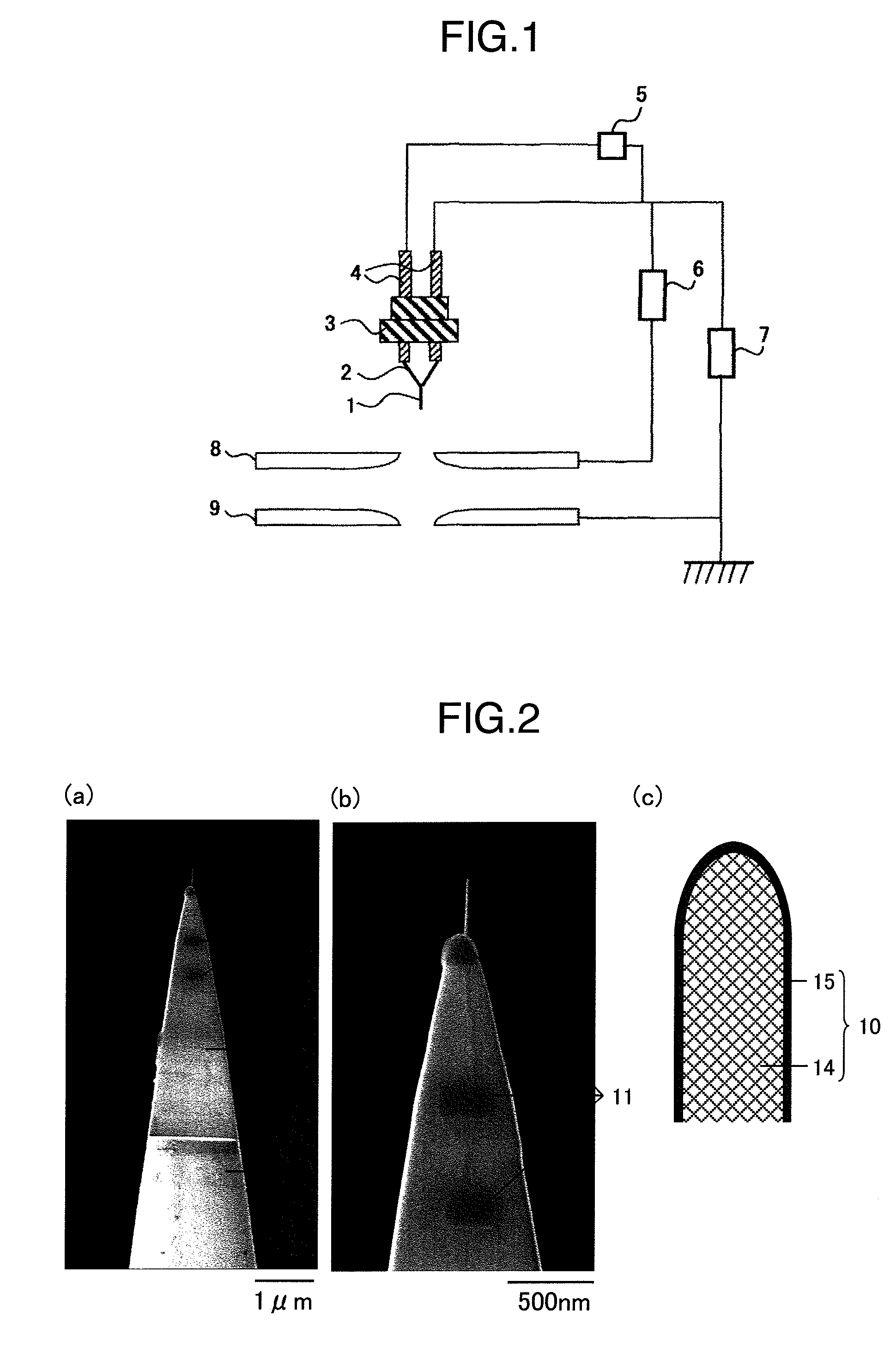
[0079]In FIG. 5, an entire configuration diagram of a scanning electron (SEM) using the above-mentioned electron gun is illustrated. In the scanning electron microscope, along an electron beam emitted from the electron gun 16, an alignment coil 17, condenser lenses 18, an astigmatic correction coil 19, deflection / scanning coils 20, an objective lens 21, and an objective diaphragm 22 are arranged. A sample 23 is set on a sample stage 24 so that the sample 23 can be irradiated with the electron beam. A secondary-electron detector is provided on a side-wall portion in a sample chamber. Moreover, the sample chamber is configured so as to be maintained under high vacuum by an exhaust system 25. From the configuration as described above, the electron beam emitted from the electron gun is accelerated at the anode, and converged by the electronic lens, then an infinitesimal area on the sample is irradiated with the electron beam. The irradiation area is two-dimensionally scanned, and such e...

example 2

[0083]In FIG. 6, an example of an entire configuration diagram of an electron beam drawing system mounting thereon an electron gun according to the present invention, is illustrated. The basic configuration of the electro-optical system thereof is substantially the same as that of the above-described scanning electron microscope. An electron beam obtained from an electron gun 16 by field emission is focused by condenser lenses 18, and converged onto a sample 23 by an objective lens 21, thus, resulting in a beam spot of nano-meter order. At that time, the center of a blanking electrode for controlling an on / off of the irradiation of the sample with electron beams should coincide with a cross-over point made by the condenser lenses.

[0084]The electron beam drawing is carried out by irradiating the sample with electron beams while controlling the on / off of the electron beams by the blanking electrode, and deflecting and scanning the electron beam on the sample by deflection / scanning coi...


PUM


Abstract

The object of the present invention is to enable the optical axis of an electron beam of a field emission electron gun mounting thereon an electron gun composed of a fibrous carbon material to be adjusted easily. Moreover, it is also to obtain an electron beam whose energy spread is narrower than that of the electron gun. Further, it is also to provide a high resolution electron beam applied device mounting thereon the field emission electron gun. The means for achieving the objects of the present invention is in that the fibrous carbon material is coated with a material having a band gap, in the field emission electron gun including an electron source composed of a fibrous carbon material and an electrically conductive base material for supporting the fibrous carbon material, an extractor for field-emitting electrons, and an accelerator for accelerating the electrons. Moreover, it is also to apply the field emission electron gun to various kinds of electron beam applied devices.

Description

FIELD OF THE INVENTION[0001]The present invention relates to a field emission electron gun and an electron beam applied device using the same.BACKGROUND OF THE INVENTION[0002]A field emission electron source composed of carbon nanotube (hereinafter, referred to as a carbon nanotube electron source) is known in that it enables higher luminance and more highly stable field emission current to be obtained than those of a known field emission electron source. However, the electron beam pattern from the carbon nanotube electron source, strongly depends on the tip-end shape of the carbon nanotube, and when the tip-end of the carbon nanotube has a closed structure and a symmetrical shape, a symmetrical and homogeneous beam pattern, as disclosed in Hata. K.: Surf. Sci. 490, pp 296-300 (2001) (non patent document 1), is obtained, since there is no technology for controlling the tip-end shape of the carbon nanotube, even if the tip-end of the carbon nanotube has a closed structure, in many ca...

Claims


Application Information

Patent Timeline
Patent Type & Authority Applications(United States)
IPC IPC(8): H01J37/073H01J37/26H01J37/30
CPCB82Y10/00B82Y40/00H01J1/3044H01J9/025H01J37/073H01J37/3174H01J2237/26H01J2201/30434H01J2201/30469H01J2201/30484H01J2201/30488H01J2201/30496H01J2237/06341H01J2201/3043
Inventor FUJIEDA, TADASHIOKAI, MAKOTOHIDAKA, KISHIOHAYASHIBARA, MITSUOWATANABE, SHUNICHI
Owner HITACHI LTD
Why Eureka
Try Eureka