Current sensor

a current sensor and current technology, applied in secondary cell servicing/maintenance, instruments, electrochemical generators, etc., can solve the problems of many manufacturing steps and cost, inability to detect a large current, and inability to use shunt resistors and resistor components, etc., to achieve accurate detection of electric current, small size, and reliable operation

Inactive Publication Date: 2008-02-07
DENSO CORP
View PDF6 Cites 78 Cited by
  • Summary
  • Abstract
  • Description
  • Claims
  • Application Information

AI Technical Summary

Benefits of technology

[0007]In view of the above-described problem, it is an object of the present invention to provide a current sensor having a high reliably, a high strength, and a small size, and manufactured at low cost.
[0010]The semiconductor bare chip is arranged in the inner room of the case body and has a detection circuit. The detection circuit detects the electric current based on a resistance of the busbar and a voltage drop across the busbar and outputs a data signal indicative of the detected electric current to the external device via the connector. The first bonding wire electrically couples the bare chip to the busbar so that the detection circuit in the bare chip can detect the electric current based on the resistance of the busbar and the voltage drop across the busbar. The second bonding wire electrically couples the bare chip to the first portion of the connector terminal of the connector so that the detection circuit in the bare chip can output the data signal to the external device via the connector.
[0011]The busbar and the detection circuit are assembled into the current sensor without soldering. In such an approach, the current sensor can avoid problems due to a cold solder and a solder whisker. Therefore, the current sensor can function reliably and accurately detect the electric current. The detection circuit is implemented on the bare chip as a monolithic integrated circuit. Thus, the current sensor can have a small size and be manufactured at low cost. The bare chip is arranged in the inner room of the case body, and the case lid covers the inner room. In such an approach, even when an external force is applied to the case body and the case lid, the bare chip can be prevented from being damaged by the external force. Therefore, the current sensor can have a high strength and function reliably.

Problems solved by technology

), the shunt resistor and the resistor member cannot be used under high temperature conditions, and cannot be used to detect a large current.
Therefore, many manufacturing steps and cost are required to solder the circuit elements to the printed circuit board, and the problems due to the cold solder and the solder whisker may occur.
Therefore, it is likely that the contact is incorrectly attached to the battery terminal during replacement of the battery.
Therefore, a large force is applied to a joint portion between the housing and the pole body and damages the joint portion.

Method used


Image

  • Current sensor
  • Current sensor
  • Current sensor

Examples


first embodiment

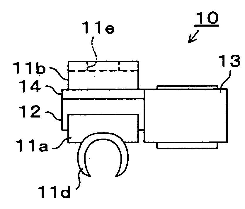
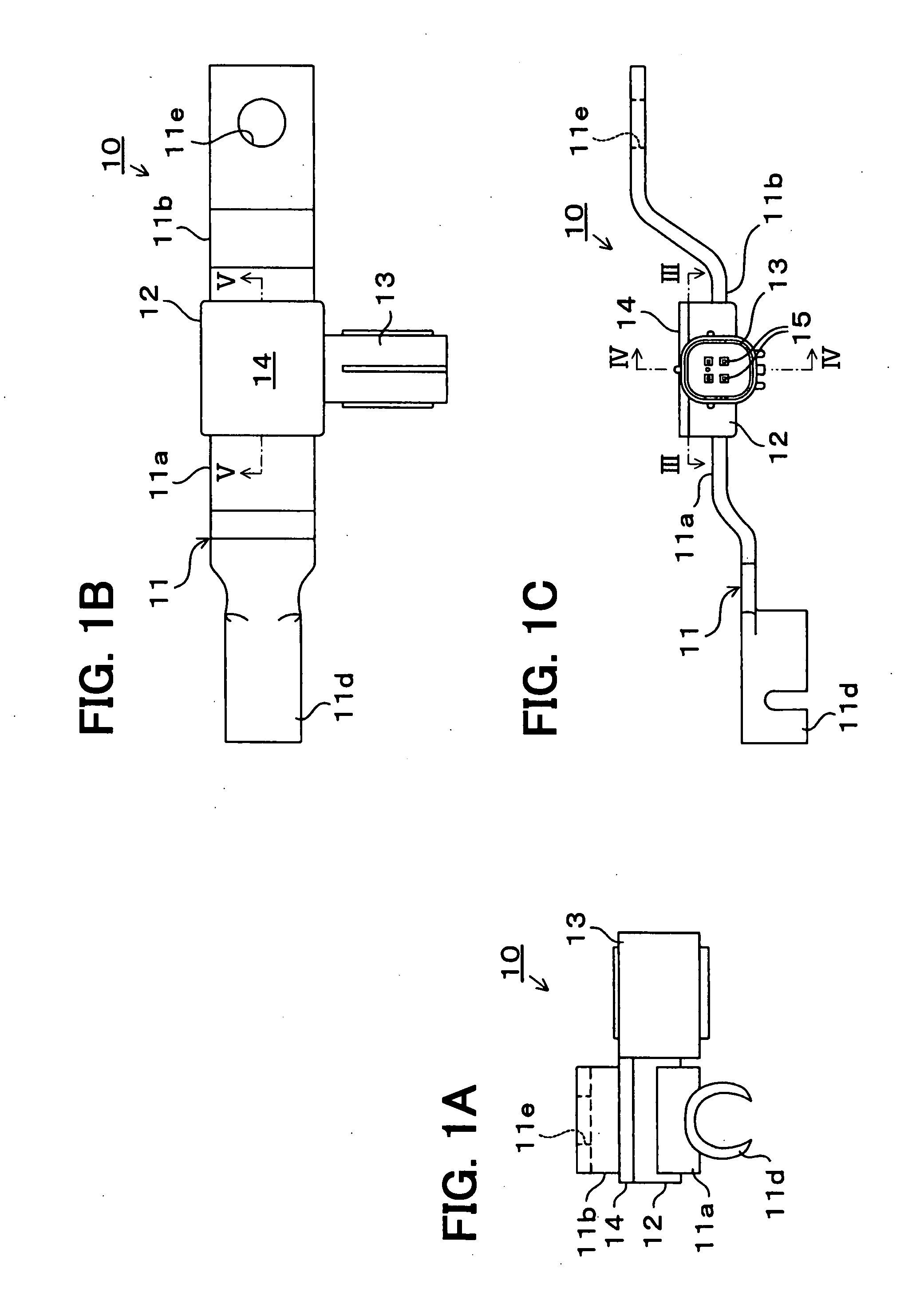
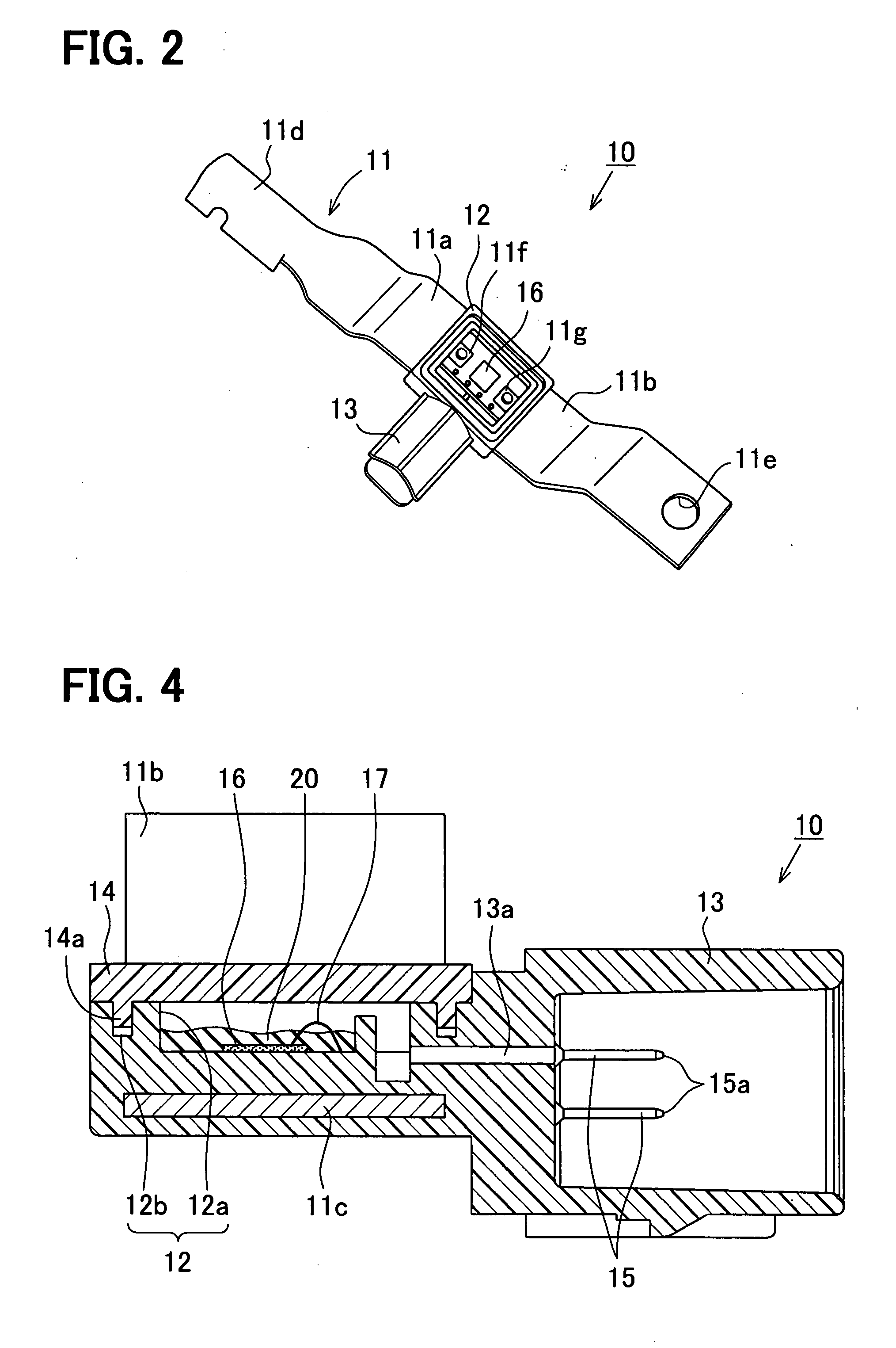
[0027]Referring to FIGS. 1A-7, a current sensor 10 according to a first embodiment of the present invention includes a busbar 11, a case body 12, a connector body 13, a case lid 14, a connector terminal 15, an integrated circuit (IC) chip 16, first and second bonding wires 17, 18, and first and second sealing members 19, 20. The current sensor 10 is used to detect, for example, charging and discharging currents of a vehicle battery.

[0028]As shown, for example, in FIG. 6C, the busbar 11 has long length and includes first and second terminals 11a, 11b, and a shunt resistor 11c. The busbar 11 forms a ground terminal of a wiring harness. Each of the first and second terminals 11a, 11b is formed by bending a rectangular metal plate made of a low resistance material such as copper, or copper alloy. The shunt resistor 11c is welded between the first and second terminals 10a, 10b. The first and second terminals 10a, 10b are bent in an opposite direction relative to the shunt resistor 11c.

[...

second embodiment

[0062]A current sensor 40 according to a second embodiment of the present invention is shown in FIGS. 9A-9C. A difference between the current sensors 10, 40 is in that the crimp terminal 11d is replaced with a bolt 41. The bolt 41 is welded to the second end of the first terminal 11a of the busbar 11 by electronic beam welding, laser welding, resistance welding, or the like. Alternatively, the bolt 41 may be unitary with the first terminal 11a of the busbar 11.

[0063]In order to connect the busbar 11 to the negative cable 32, the bolt 41 is inserted through a mounting hole of a ring terminal (not shown) attached to the negative cable 32. A nut (not shown) is then tightened onto the bolt 41 so that the busbar 11 can be electrically connected to the negative cable 32.

[0064]According to the second embodiment, the busbar 11 is connected to the negative cable 32 by the bolt 41 instead of the crimp terminal 11d. In such an approach, the current sensor 40 can be attached to and detached fro...

third embodiment

[0065]A current sensor 50 according to a third embodiment of the present invention is shown in FIGS. 10A-10C. A difference between the current sensor 50 and the current sensor 10 of the first embodiment is in that the crimp terminal 11d is replaced with a ring terminal 51. The ring terminal 51 has a mounting hole.

[0066]In order to connect the busbar 11 to the negative cable 32, a bolt (not shown) is inserted through the mounting hole of the ring terminal 51 and a mounting hole of a ring terminal (not shown) attached to the negative cable 32. A nut (not shown) is then tightened onto the bolt so that the busbar 11 can be electrically connected to the negative cable 32.

[0067]According to the third embodiment, the busbar 11 is connected to the negative cable 32 by the ring terminal 51 instead of the crimp terminal 11d. In such an approach, the current sensor 50 can be attached to and detached from the negative cable 32 according to needs.


PUM


Abstract

A current sensor includes a busbar, a case, a connector, and a bare chip having a current detection circuit. The busbar has a crimp terminal at one end, a ring terminal at the other end, and a shunt resistor welded between the crimp and ring terminals. The shunt resistor is encapsulated in the case, and the busbar has an electrode exposed to a sealed inner room of the case. The connector has a connector body unitary with the case and has a connector terminal that is exposed to the inner room at one end and exposed to an outside of the connector body at the other end. The bare chip is arranged in the inner room of the case and wire-bonded to each of the busbar and the connector terminal.

Description

CROSS REFERENCE TO RELATED APPLICATION[0001]This application is based on and incorporates herein by reference Japanese Patent Application No. 2006-213574 filed on Aug. 4, 2006.FIELD OF THE INVENTION[0002]The present invention relates to a current sensor for measuring an electric current flowing through a busbar based on a resistance of the busbar and a voltage drop across the busbar.BACKGROUND OF THE INVENTION[0003]A current sensor has been proposed that detects an electric current flowing through a shunt resistor based on a resistance of the shunt resistor and a voltage drop across the shunt resistor. For example, this type of current sensor is used to detect charging and discharging currents of a vehicle battery, or an excitation current of an electric motor installed in an electric hybrid vehicle (EHV) and an electric vehicle (EV).[0004]A shunt resistor disclosed in JP-A-H8-115802 includes L-shaped legs and has a low temperature coefficient. The shunt resistor is surface-mounted ...

Claims


Application Information

Patent Timeline
Patent Type & Authority Applications(United States)
IPC IPC(8): G01R19/00
CPCG01R1/203G01R19/16542H01R11/287H01M10/425H01M10/48G01R31/3696H01L2224/48091H01L2224/49171G01R31/364Y02E60/10H01L2924/00014
Inventor ARATANI, MASAHIRO
Owner DENSO CORP
Why Eureka
Try Eureka