Photocatalytic fabric

a photocatalytic fabric and fabric technology, applied in the direction of physical/chemical process catalysts, separation processes, knitting, etc., can solve the problems of organic compound breakage and bacteria damage, and achieve the effect of greatly increasing the surface area of tio2 exposed to the fluid

a photocatalytic fabric and fabric technology, applied in the direction of physical/chemical process catalysts, separation processes, knitting, etc., can solve the problems of organic compound breakage and bacteria damage, and achieve the effect of greatly increasing the surface area of tio2 exposed to the fluid

US20080031783A1Inactive Publication Date: 2008-02-07BRIGGS DANIEL J +1

Image

  • Photocatalytic fabric
  • Photocatalytic fabric
  • Photocatalytic fabric

Examples


Embodiment Construction

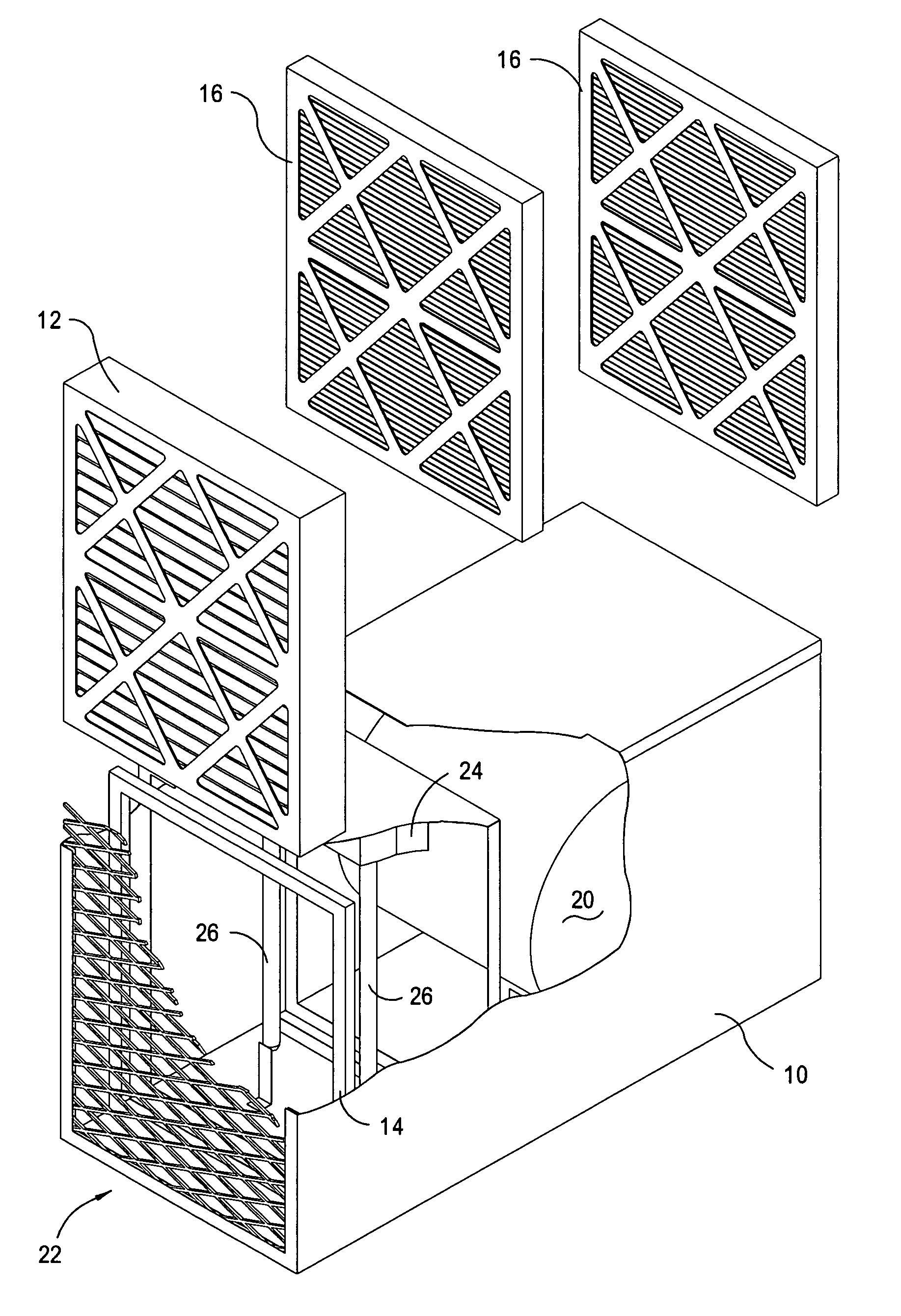
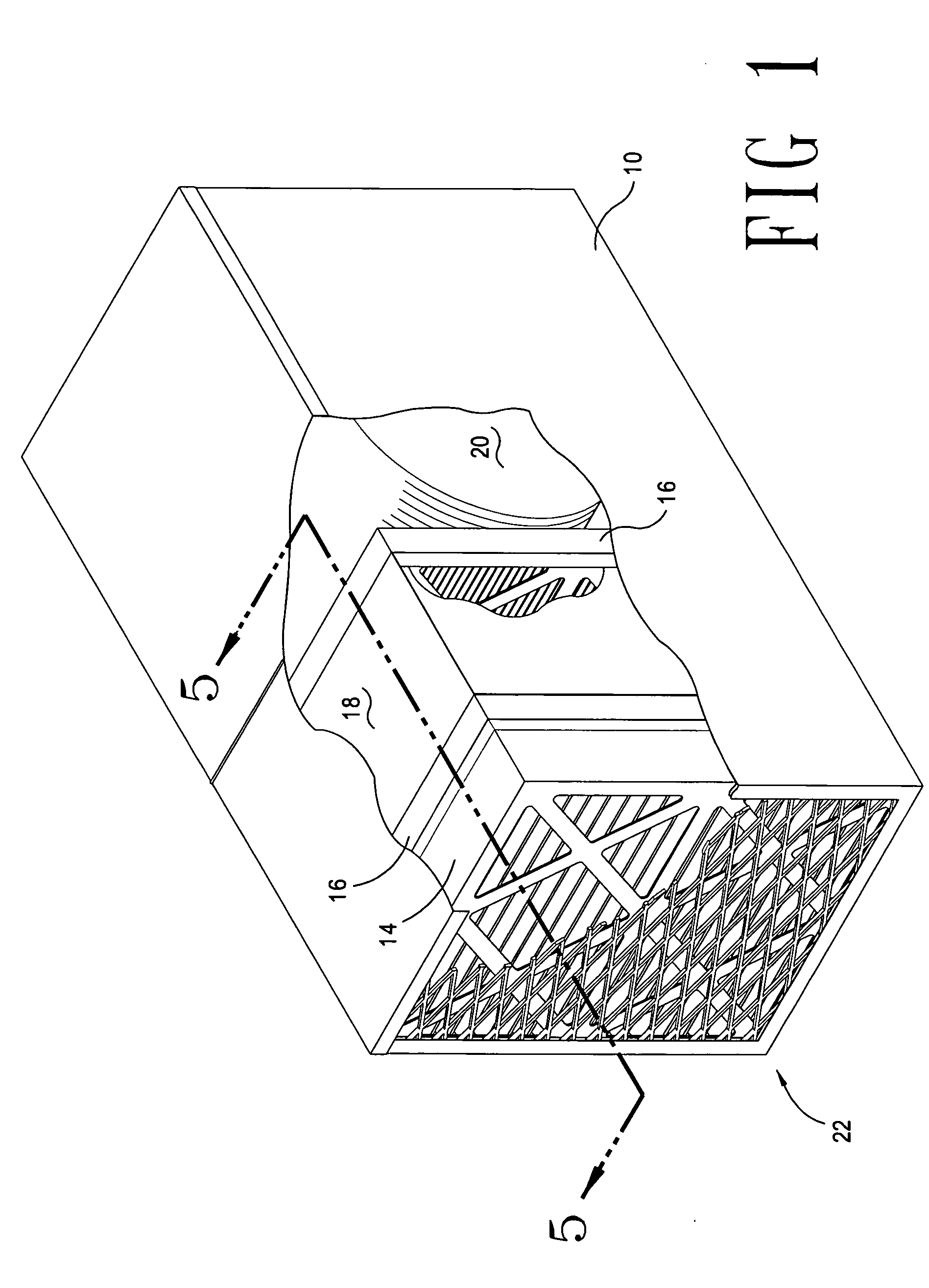
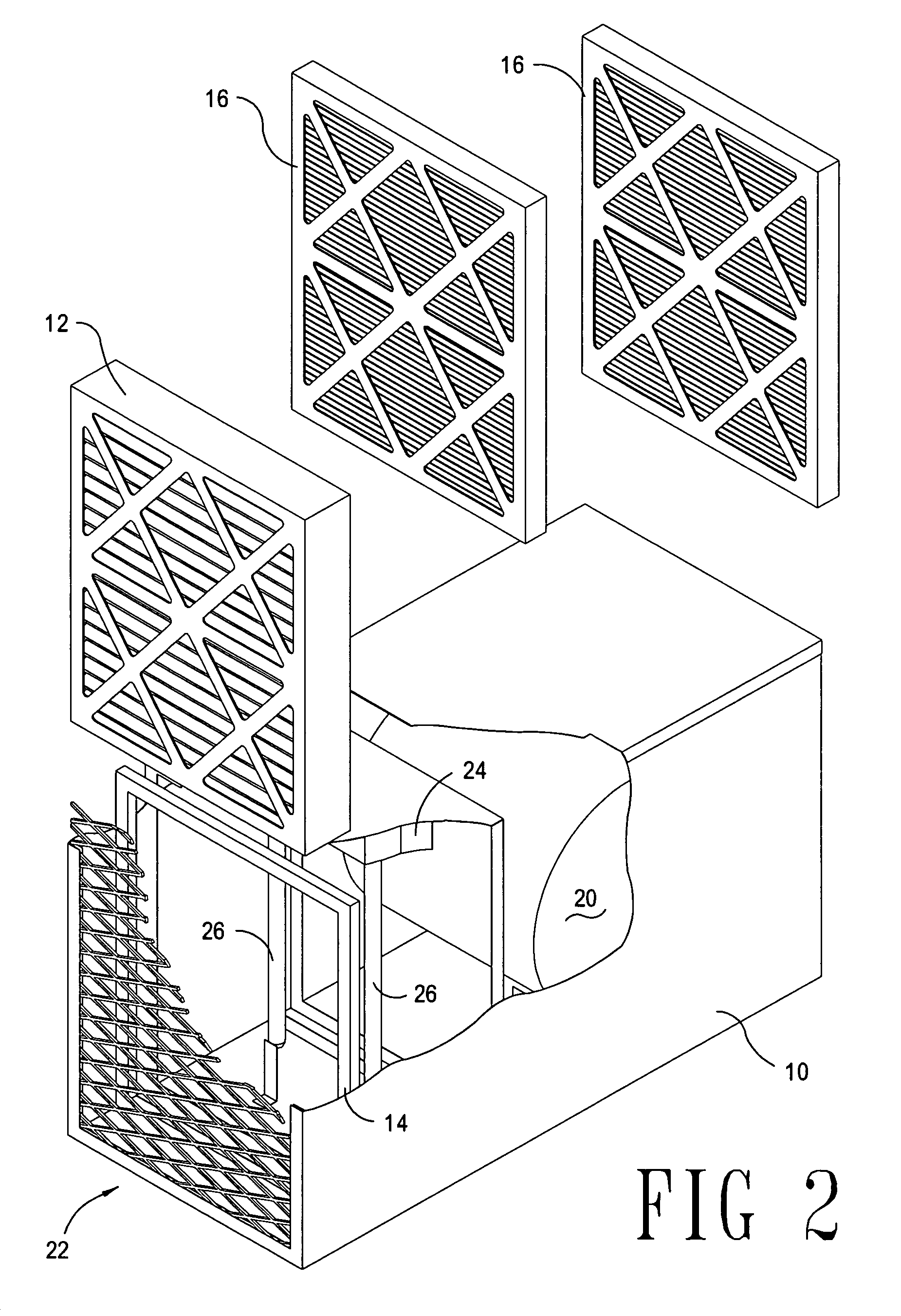
[0020]Referring to FIGS. 1, 2, and 4, the instant Invention comprises an enclosure (unit housing) 10 having a top, two sides, a bottom, as well as a forward opening (air inlet) 22 and a rear exhaust (air duct) 48. The enclosure 10 includes a conventional air filter 12, an ultraviolet photocatalytic chamber 34, and means for moving a fluid stream through the enclosure 20. It will be understood that while the instant invention is preferably used to purify a fluid stream which is gaseous in nature, the same principles may apply to removal of contaminants from a liquid fluid stream. The forward opening 22 allows a gas containing contaminant particulates 42 and microscopic particulates 44 to pass into the apparatus by flowing initially through the air filter 12. The air filter 12 is housed between the forward opening 22 and an air sealant 14, which is essentially a flange running around the interior diameter of the enclosure 10. The contaminant particulates 42 are macroscopic contaminant...


PUM

PropertyMeasurementUnit
wavelengthsaaaaaaaaaa
transparentaaaaaaaaaa
sizeaaaaaaaaaa

Abstract

A multipurpose air sterilization machine is disclosed comprising an enclosure holding a pre-filter, an ultraviolet light chamber with a plurality of ultraviolet lights, one or more photocatalytic oxidizing scrims, and a blower. Air is pulled through the machine by the blower, and passes first through the pre-filter, then the first scrim, then one or more ultraviolet light chambers defined by the plurality of scrims, and is ultimately expelled from the rear of the machine after passing through the blower. The scrims provide for enhanced ultraviolet decomposition of organic compounds, including bacteria, mold spores, viruses, and other organisms, and comprises a substrate coated with a photocatalytic material such as TiO2 adhered to the surface with an ultraviolet-transparent organic polymer.

Description

REFERENCE TO PRIOR APPLICATIONS[0001]Reference is hereby made to Provisional application No. 60 / 424,270, filed Apr. 2, 2004, from which priority is claimed pursuant to 35 U.S.C. § 120.STATEMENT REGARDING FEDERALLY SPONSORED RESEARCH[0002]Not Applicable.REFERENCE TO “MICROFICHE APPENDIX”[0003]Not Applicable.BACKGROUND OF THE INVENTION[0004]This Invention relates to devices for purifying and sterilizing air using a photocatalytic scrim formed by coating a substrate with titanium dioxide (TiO2). Purification and sterilization of air is beneficial for a number of applications from the medical field to home / consumer use. In the medical field, for instance, hospitals rely on sterilization to prevent infection of patients undergoing surgery. Given that a hospital, by its nature, has a large concentration of sick persons, air sterilization is desirable to minimize the risks of diseases being communicated to noninfected persons, both patients and staff. In commercial use, air purification te...

Claims


Application Information

Patent Timeline
07 Feb 2008
Publication
US20080031783A1
IPC
A61L9/20; B32B5/02; D03D9/00
CPC
A61L9/205; B01D53/007; B01D53/885; B01D2255/20707; B01D2255/802; D06N3/0063; B01D2259/804; B01J21/063
Inventors
BRIGGS, DANIEL J.; VARNERIN, CARL F.