System and method for controlling the size and/or distribution of catalyst nanoparticles for nanostructure growth

a nanoparticle and catalyst technology, applied in the field of systems, can solve the problems of inability to provide controllable and predictable carbon nanotube growth in terms of size and density, prior proposed schemes are difficult to integrate into conventional semiconductor device fabrication methodologies, and it is inconceivable that iron catalyst particles will be uniformly distributed across a wafer without further aid

Inactive Publication Date: 2008-02-07
AGILENT TECH INC
View PDF4 Cites 66 Cited by
  • Summary
  • Abstract
  • Description
  • Claims
  • Application Information

AI Technical Summary

Benefits of technology

[0010]As mentioned above, nanostructures, such as carbon nanotubes, are grown from catalyst nanoparticles on a substrate via a growth process such as CVD or PECVD. Embodiments of the present invention provide techniques for controlling the size and / or distribution (e.g., density, relative spacing, etc.) of such catalyst nanoparticles on a substrate. More particularly, techniques are provided in which polymers are used as a carrier of a catalyst payload, and such catalyst-containing polymers self-assemble on a substrate thereby controlling the size and / or distribution of the catalyst nanoparticles in a desired manner. In exemplary embodiments described herein, block copolymers capable of self-assembly are used as a carrier of catalyst species (e.g., atoms of a catalyst, such as iron, cobalt, nickel, etc.). The copolymers self-assemble to condense and arrange the catalyst species into a distribution of catalyst nanoparticles. The non-catalyst material (e.g., organic materials) are removed, leaving the catalyst nanoparticles remaining distributed on the substrate. Accordingly, the self-assembly of the polymers controls the size and distribution of the catalyst nanoparticles formed on the substrate.

Problems solved by technology

Traditional nanotube growth methods suffer from the intrinsic inability to provide controllable and predictable carbon nanotube growth in terms of size and density.
Prior proposed schemes are also very difficult to integrate into conventional semiconductor device fabrication methodology, especially when catalyst supports are used.
Even though the particle size control is improved in these techniques, it is inconceivable that iron catalyst particles will be uniformly distributed across a wafer without further aid, such as with the aid of a polymer binder.
Dip coating of Poly(styrene-block-ferrocenylethylmethylsilane) has been proposed to form short-range ordered self-assembled structures, but long-range order has not been achieved in this manner.

Method used


Image

  • System and method for controlling the size and/or distribution of catalyst nanoparticles for nanostructure growth
  • System and method for controlling the size and/or distribution of catalyst nanoparticles for nanostructure growth
  • System and method for controlling the size and/or distribution of catalyst nanoparticles for nanostructure growth

Examples


Embodiment Construction

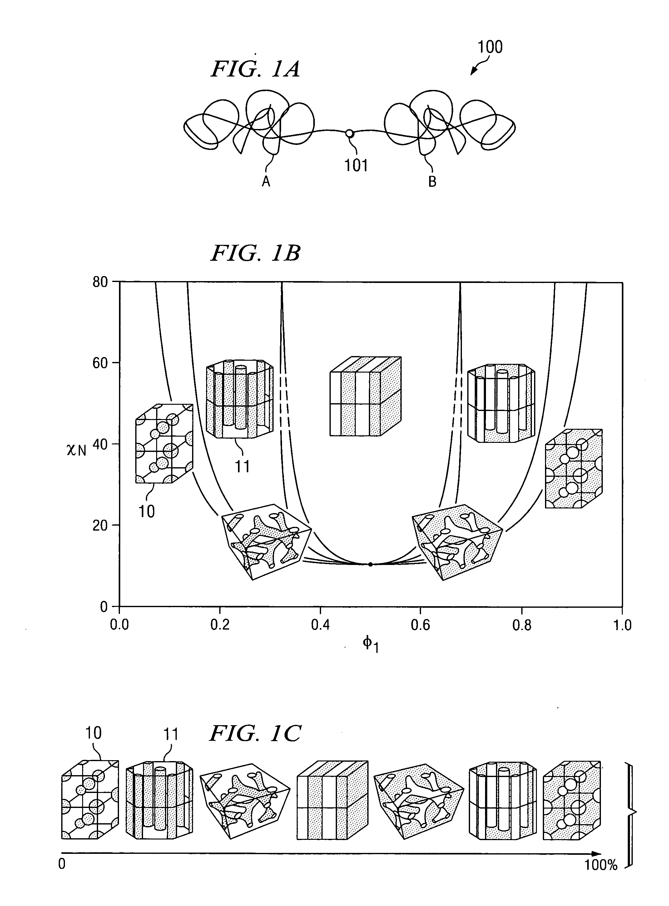
[0031]It is helpful at the outset hereof to provide an overview of some of the terminology used herein. The following overview of terminology will be a simple review for one of ordinary skill in the art, as the terminology used herein is not inconsistent with how it is commonly used in the art.

[0032]The term “polymer” refers to a chemical compound or mixture of compounds formed by polymerization and consisting essentially of repeating structural units. The basic chemical “units” that are used in building a polymer are referred to as “repeat units.” A polymer may have a large number of repeat units or a polymer may have relatively few repeat units, in which case the polymer is often referred to as an “oligomer.”

[0033]When a polymer is made by linking only one type of repeat unit together, it is referred to as a “homopolymer.” When two (or more) different types of repeat units are joined in the same polymer chain, the polymer is called a “copolymer.” In copolymers, the different types...


PUM

PropertyMeasurementUnit
diametersaaaaaaaaaa
sizeaaaaaaaaaa
sizeaaaaaaaaaa

Abstract

Techniques for controlling the size and / or distribution of a catalyst nanoparticles on a substrate are provided. The catalyst nanoparticles comprise any species that can be used for growing a nanostructure, such as a nanotube, on the substrate surface. Polymers are used as a carrier of a catalyst payload, and such polymers self-assemble on a substrate thereby controlling the size and / or distribution of resulting catalyst nanoparticles. Amphiphilic block copolymers are known self-assembly systems, in which chemically-distinct blocks microphase-separate into a nanoscale morphology, such as cylindrical or spherical, depending on the polymer chemistry and molecular weight. Such block copolymers are used as a carrier of a catalyst payload, and their self-assembly into a nanoscale morphology controls size and / or distribution of resulting catalyst nanoparticles onto a substrate.

Description

CROSS-REFERENCE TO RELATED APPLICATIONS[0001]This application claims priority to U.S. Provisional Patent Application Ser. No. 60 / 631,247 entitled “METHOD FOR PRODUCING UNIFORMLY DISTRIBUTED NANOTUBES CATALYSTS ACROSS A SURFACE AND PATTERNING THE SAME”, filed Nov. 23, 2004, the disclosure of which is hereby incorporated herein by reference. This application is also related to U.S. patent application Ser. No. 10 / 766,639 entitled “NANOSTRUCTURES AND METHODS OF MAKING THE SAME”, filed Jan. 28, 2004, the disclosure of which is hereby incorporated herein by reference.BACKGROUND OF THE INVENTION[0002]Carbon nanotubes (CNTs) have become the most studied structures in the field of nanotechnology due to their remarkable electrical, thermal, and mechanical properties. In general, a carbon nanotube can be visualized as a sheet of hexagonal graph paper rolled up into a seamless tube and joined. Each line on the graph paper represents a carbon-carbon bond, and each intersection point represents a...

Claims


Application Information

Patent Timeline
Patent Type & Authority Applications(United States)
IPC IPC(8): B05D7/22G03C5/00
CPCB82Y30/00B01J35/0013
Inventor LU, JENNIFER Q.MOLL, NICOLAS J.ROITMAN, DANIEL B.DUTTON, DAVID T.
Owner AGILENT TECH INC
Why Eureka
Try Eureka