Miniaturized Apparatus For Real-Time Monitoring

a real-time monitoring and miniature technology, applied in the field of continuous real-time quantitative monitoring apparatus, can solve the problems of difference in the progress of polymerase chain reaction, inability to put other reaction mixtures into the apparatus, poor measurement accuracy of the progress of the reaction, etc., to achieve the effect of improving the reproducibility and stabilization of the reaction, reducing the elapsed time of the reaction, and improving the reactivity

Inactive Publication Date: 2008-02-07
BIONEER
View PDF3 Cites 41 Cited by
  • Summary
  • Abstract
  • Description
  • Claims
  • Application Information

AI Technical Summary

Benefits of technology

[0047] In the apparatus of the present invention, the progress of reaction can be measured per each cycle, by measuring the intensity of fluorescence generated from each capillary tube after the reaction mixture was sequentially flowed through the capillary tube with a certain time interval.
[0048] The present invention is related to the apparatus which can be effectively used in the fields (e.g. detecting the pathogenic microorganisms in the air, monitoring the water pollution, detection and identification of the biological terror, and others) which require continuous collection and measurement of the reaction mixture with a certain time interval. This apparatus can be effectively used in the above industrial fields as the conventional technique which cannot process the reaction of reaction mixture with a certain time interval was dramatically improved.
[0049] In addition, the apparatus of the present invention can greatly minimize the elapsed time for the reaction, as only small amount of reaction mixture flows within the capillary tube, and the above apparatus can increase the reproducibility and stabilization of the reaction by improving the problem of the conventional apparatus that there can be difference in conducting of heat due to the space between the thermal conduction block and a reaction vessel, by coiling the capillary tube in order around the thermal conduction block (120).
[0050] In addition, in the reactivity can be improved and the special reaction such as pre-treatment reaction can be realized, by adapting a heating block (170) and reaction mixture pretreatment block (180) separately, and also it is possible to measure the progress of the reaction of numerous reaction mixtures and many reaction cycles at once, by concurrently measuring the intensity of the fluorescence generated from numerous capillary tubes with the linear type of sensor.
[0051] In addition, in the case that numerous reaction mixtures are measured concurrently in the apparatus of the present invention, it is possible to measure the progress of the reaction for each reaction mixture by sequentially flowing the above reaction mixtures through the capillary tube separately.

Problems solved by technology

However, the real-time monitoring apparatus for the Polymerase Chain Reaction which have been known to the public until now, have several problems that they cannot treat reaction mixture sequentially with a certain time interval whereas they can treat a large number of reaction mixture, and that other reaction mixture cannot be put into the apparatus until the reaction of the preceding mixture is completed.
Consequently, it provides a poor accuracy in measurement of the progress of the reaction, since measuring fluorescence of a number of reaction mixture takes a longer period of time.
The common problems of this type of techniques are that it is required to rotate a thermal conduction block for the Polymerase Chain Reaction and that there may be a difference in the progress of the Polymerase Chain Reaction owing to the difference of contact between each capillary and thermal conduction block, which causes the decline of reproducibility.
In addition, it is unable to perform the Polymerase Chain Reaction continuously with a certain time interval in this type of apparatus.
Moreover, there is a serious problem that it is unable to check the progress of reaction until the reaction is completed.
These optical apparatuses which are used for radiation and to control and adjust the light channel are not only expensive but also take considerable space.
Moreover, these driving means, power transmission means, transporting apparatus, and etc. also cause the problem of the space required for an apparatus for the Polymerase Chain Reaction, because these mechanical apparatuses and linear motor apparatuses make the Polymerase Chain Reaction machine large in size and may cause frequent breakdown and malfunction.
Another cause of raising the production cost of the Polymerase Chain Reaction machine is the delicate mechanical processing on installation.
Such scanning method causes problems such as that light may be radiated during the scanning process, that it can only monitor the reaction within the capillary tube when the fluorometer passes and that it cannot monitor the reaction that occurs at the other part within the capillary tube where the scanner cannot cover.

Method used


Image

  • Miniaturized Apparatus For Real-Time Monitoring
  • Miniaturized Apparatus For Real-Time Monitoring
  • Miniaturized Apparatus For Real-Time Monitoring

Examples


example 1

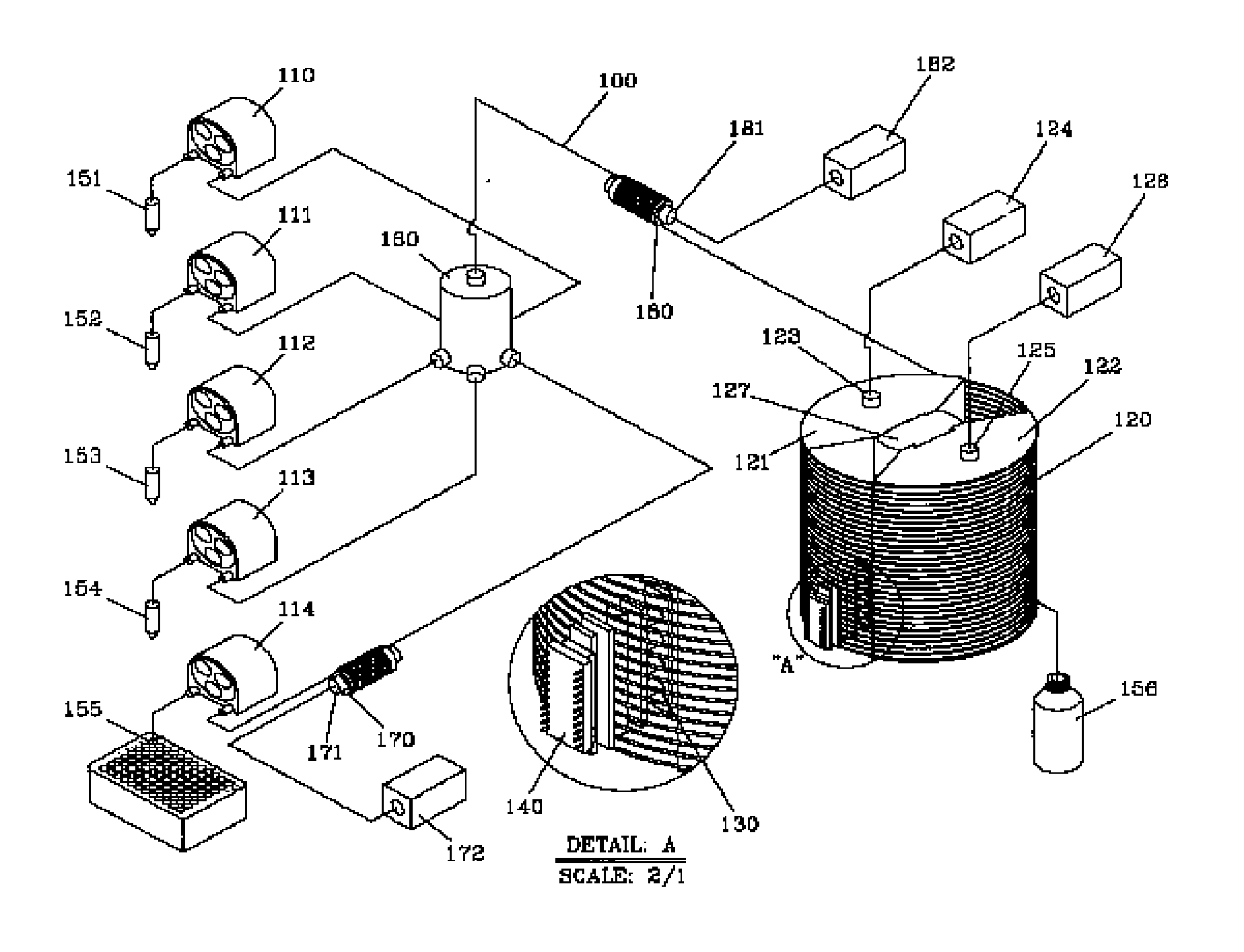
[0089] In the case that the Polymerase Chain Reaction was performed through the present invention, the constitutional and the functional scheme which enables simultaneously all the every progress of each cycle for one kind of reaction mixture, not by measuring per every cycle, when the reaction is completed, comprises the following steps.

[0090] At first, the detergent (154) is transferred within the capillary tube to wash capillary tube by using a quantitative pump (113); then the quantitative pump (112) connected to distilled water (153) for washing was operated to push distilled water within the capillary tube until the distilled water reached the wastewater bottle (156); thereby the process to wash the inside of the capillary tube was completed.

[0091] Then, constant quantity of the reaction reagent (151) and the reaction mixture (155) was inputted within the capillary tube by using the quantitative pumps (110 and 114) alternately. In this progress, the above quantity was limite...

example 2

[0094] The following is the constitutional and functional scheme of the present invention to measure numerous reaction mixtures continuously with a certain time interval.

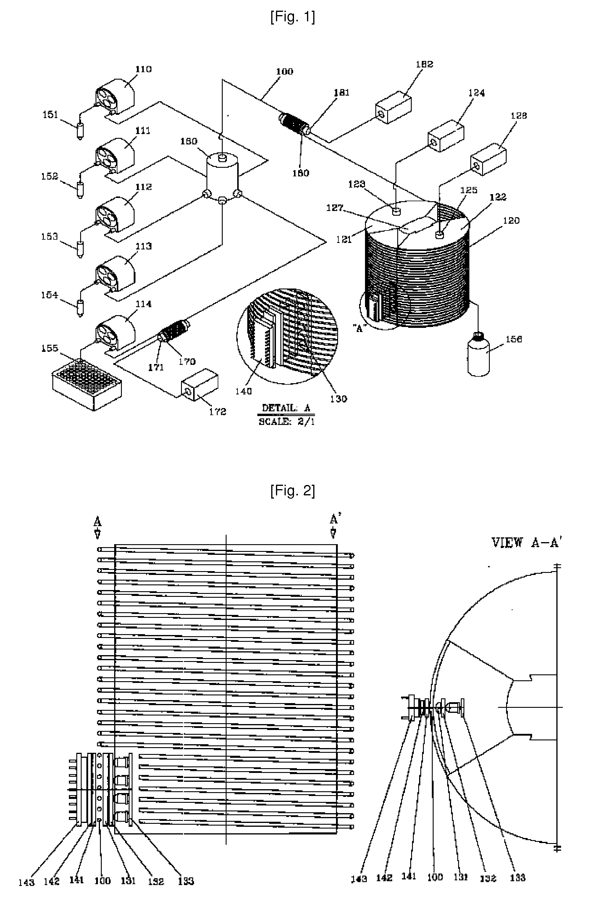
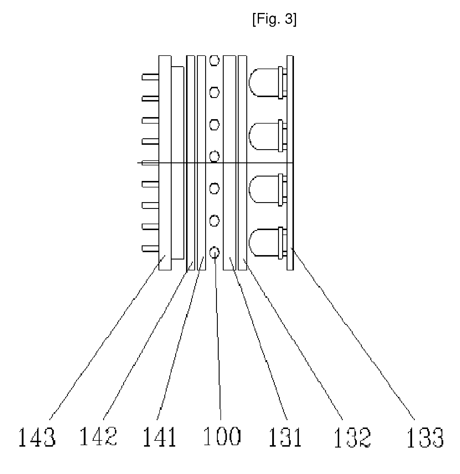
[0095] The process to wash capillary tube was same as example 1. After washing, the certain quantity of reaction reagent (151) and reaction mixture (155) was inputted within the capillary tube by operating the quantitative pump (110 and 114) alternatively. During the above process, The scope of quantity of the inputted reaction reagent and reaction mixture should be above the scope wherein the above reaction reagent and reaction mixture can be detected by the light receiving section (140), and should be under the scope of a certain amount for one (1) cycle of the capillary tube coiling around the thermal conduction block (120). The rest part of total amount of the reaction mixture was filled with mineral oil (152), thereby the amount for one (1) reaction cycle was prepared and then inputted within the capillary tub...


PUM

PropertyMeasurementUnit
temperatureaaaaaaaaaa

Abstract

The present invention relates to a apparatus for quantitative continuous real-time monitoring to monitor a continuous reaction of biochemical reagent and the reaction, such as DNA. More particularly, the present invention is directed to a miniaturized apparatus for real-time monitoring of biochemical reaction, which comprises capillary tubes (100) wherein biochemical reaction mixture flow; a thermal conduction block (120) which is coiled with capillary tube several rounds in order and composed of several blocks for temperature control of which temperatures are different from each other for heating or cooling the biochemical reaction mixture which flow in capillary tube, and a temperature controller which controls the temperature of above temperature control block; a radiation part (130) to radiate the reaction mixture flowing through the capillary tube and a light receiving section (140) which receives and measures the intensity of the fluorescence generated from the capillary tubes.

Description

TECHNICAL FIELD [0001] The present invention relates to a continuous real-time quantitative monitoring apparatus to monitor a continuous reaction of biochemical reagent and the reaction product thereof, such as DNA. More particularly, the present invention is directed to a miniaturized apparatus for real-time monitoring of biochemical reaction, which comprises capillary tubes (100) wherein the biochemical reaction mixture flow; a thermal conduction block (120) which is coiled with capillary tube several rounds in order and composed of several blocks for temperature control of which temperatures are different from each other for heating or cooling the biochemical reaction mixture which flow in capillary tube, and a temperature controller which controls the temperature of above temperature control block; a radiation part (130) to radiate the reaction mixture flowing through the capillary tube and a light receiving section (140) which receives and measures the intensity of the fluoresc...

Claims


Application Information

Patent Timeline
Patent Type & Authority Applications(United States)
IPC IPC(8): G01N21/64B01J19/00
CPCB01L3/5025B01L7/525G01N21/645B01L2300/0841B01L2300/087B01L2300/0838C12Q1/6846C12Q1/6851
Inventor PARK, HAN OHPARK, HANEEBAEK, JONG SOO
Owner BIONEER
Why Eureka
Try Eureka