Automated laser-treatment system with real-time integrated 3D vision system for laser debridement and the like

a laser treatment and laser head technology, applied in the field of automatic control of laser heads, can solve the problems of significant cosmetic and/or functional deficits, significant increase in blood flow to the skin, and much greater blood loss, and achieve the effect of reducing the logistical burden of medical car

Active Publication Date: 2008-02-07
OMNITEK PARTNERS LLC
View PDF10 Cites 128 Cited by
  • Summary
  • Abstract
  • Description
  • Claims
  • Application Information

AI Technical Summary

Benefits of technology

[0022] There is also a need for automated laser debridement systems for the treatment of chemical and thermal burn injuries to significantly reduce medical logistical burden, especially in a mass casualty scenario.

Problems solved by technology

Vesicant injuries in particular can take several months to heal, necessitating lengthy hospitalizations, and result in significant cosmetic and / or functional deficits.
The reason for this is that the very presence of the dead skin causes an inflammatory reaction which results in a significant increase in blood flow to the skin.
Consequently, when burned skin is excised from the body after 7-10 days there is a much greater blood loss.
However this method is time consuming in large burns and is often associated with the loss of considerable amounts of blood.
At lower fluences there is more desiccation and carbonization and a higher likelihood of scarring.
Epidermal lesions can be ablated accurately, but deeper peels may be limited by intraoperative bleeding due to the relatively thin layer of residual thermal damage.
However, the thickness of subsequent fibrosis or ‘collagen remodeling’ is greater in CO2 laser-treated sites, possibly reflecting greater underlying thermal damage.
One major drawback of all currently available laser systems is that they require the physician and / or surgeon to move a hand piece over the damaged area, which is very time-consuming given an injury with a large surface area.
The design of small hand held scanners on the ends of articulated arms has weakened this drawback to a limited extent.
However, the scanned areas are relatively small and the physician / surgeon still needs to move the scanner head over relatively large treatment areas.
In fact, certain laser treatment processes are so slow that they are effectively impractical for treating patients.

Method used


Image

  • Automated laser-treatment system with real-time integrated 3D vision system for laser debridement and the like
  • Automated laser-treatment system with real-time integrated 3D vision system for laser debridement and the like
  • Automated laser-treatment system with real-time integrated 3D vision system for laser debridement and the like

Examples


embodiment 140

[0095] It is appreciated by those familiar with the art that even though an arc-type and two rail gantry system is shown in the schematics of the embodiment 140, any other gantry type (such as one rail type) or any other type of such robotic system may be used instead. This embodiment can be suitable for hospitals or other similar settings due to the total size and weight of the system. The gantry system can be integrated into the structure of the bed.

[0096] The primary advantage of the embodiment 140 over the embodiments 100 and 120 is that the geometric relationship of the 3D vision system camera and projector system 142 with the laser scanner head 143 is fixed in the ILSRTV system and pre-calibrated. Once the treatment area 148 and its 3D geometry are determined, a simple algorithm is used to plan the scanning path of the laser beam 145. During the treatment process, the scanning path of the laser beam 145 is constantly corrected to account for potential body motions of the subje...

embodiment 200

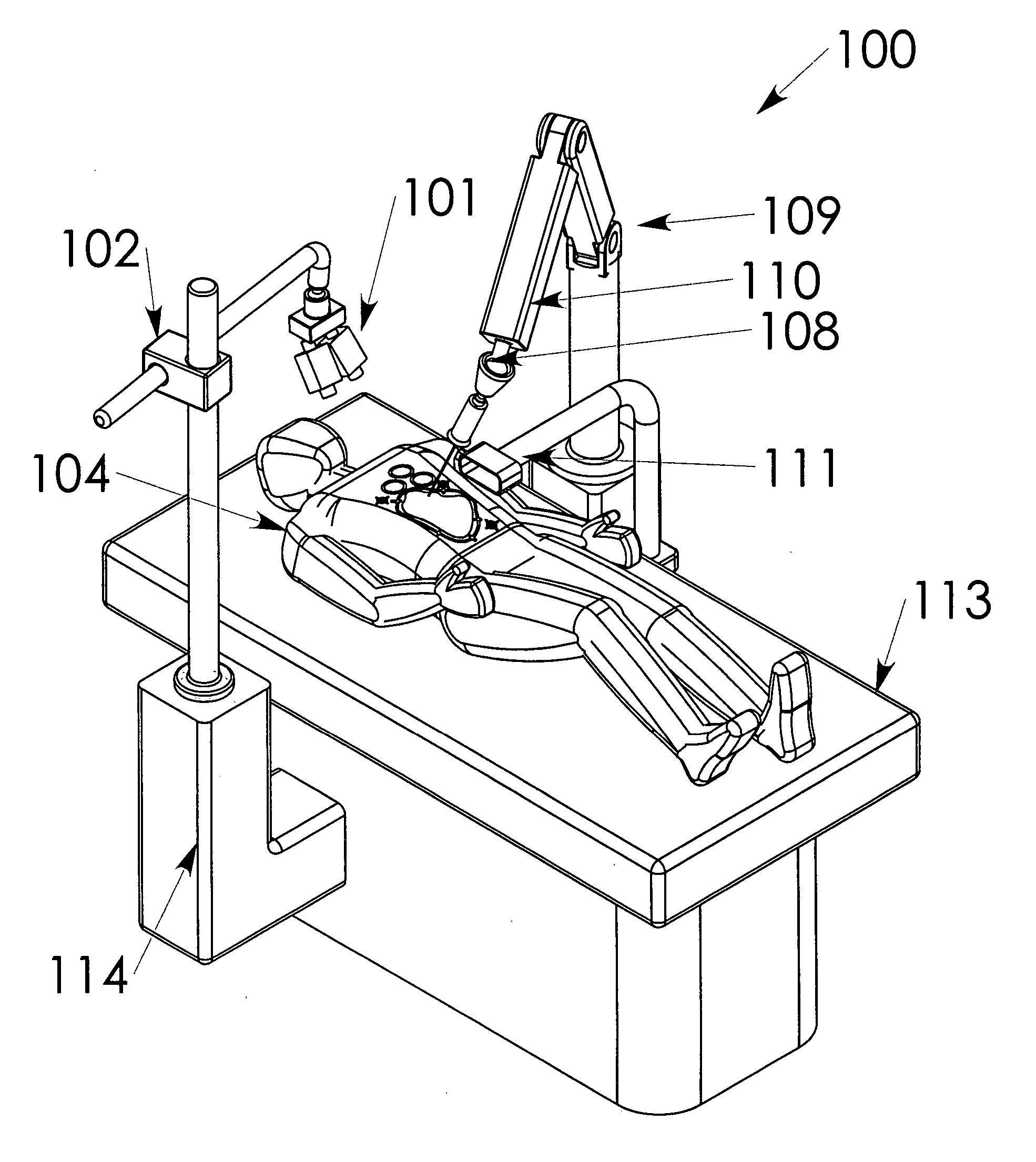
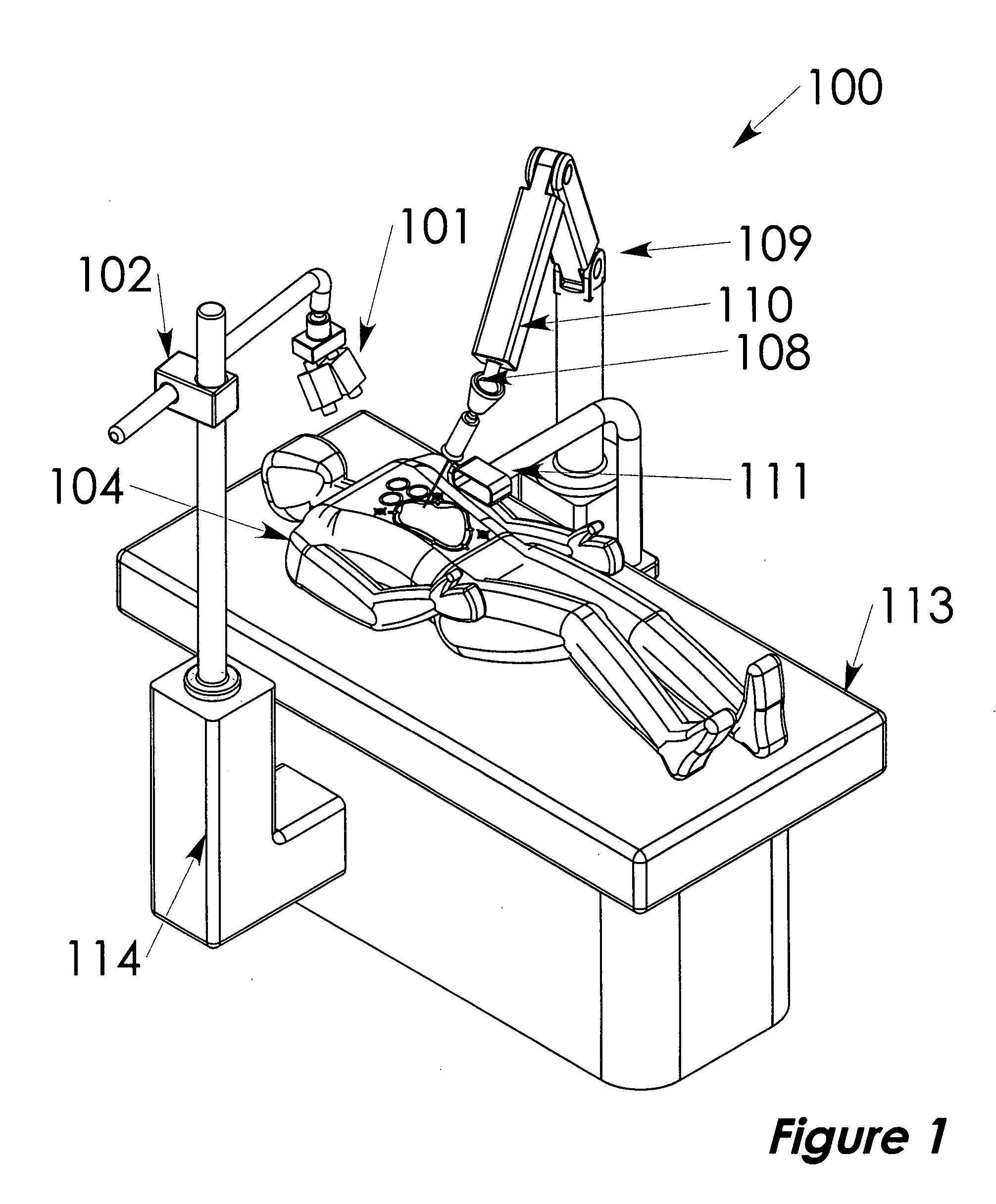
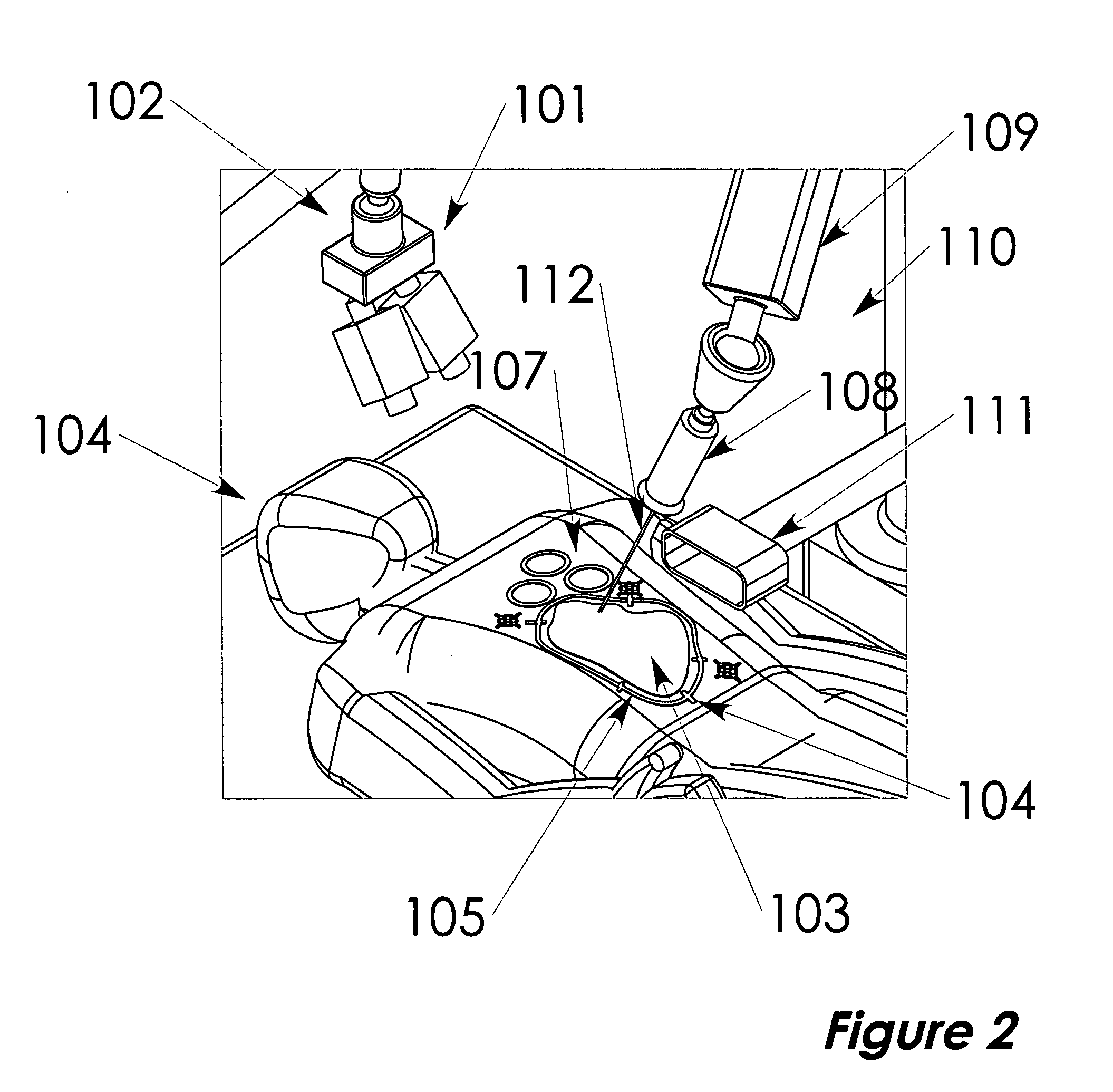
[0108] Still yet another embodiment 200 of the present invention is shown in FIG. 7. FIG. 8 shows the general positioning of the embodiment 200 during the treatment of a patient 201 laying over the bed 202. The system 200 is designed to be self-contained, requiring only electrical power for operation. The system 200, with its articulating arm stowed over the base cabinet, can be readily stored or moved to a side until it is needed again. The setup of the system 200 will generally proceed as follows: [0109] 1. Wheel the system 200 into approximate position and lock wheels 203. [0110] 2. Grasp treatment head handle(s) 204 and depress button (not shown) to unlock joints 205 of articulating arm 206. Such articulating arms are well known in the art. [0111] 3. Position treatment head 207 such that the bottom periphery of the laser shield 208 is close to the patient 201 and envelopes the desired treatment area. [0112] 4. Position the LCD touch screen 209 in a convenient location such that ...


PUM


Abstract

A method for automated treatment of an area of skin of a patient with laser energy. The method including: identifying the area to be treated with the laser; modeling the identified area of the skin to be treated; and controlling the laser to direct laser energy to within the modeled area of the skin.

Description

CROSS-REFERENCE TO RELATED APPLICATIONS [0001] The present application claims priority to U.S. provisional patent application, Ser. No. 60 / 835,024, filed on Aug. 2, 2006, the entire contents of which is incorporated herein by reference.BACKGROUND OF THE INVENTION [0002] 1. Field of the Invention [0003] The present invention relates generally to automated control of a laser head for treatments on human skin, and more particularly to automated control of a laser head for laser debridement of burns. [0004] 2. Prior Art [0005] Thermal burns and vesicating (blistering) due to chemical warfare agents such as sulfur mustard and Lewisite induced skin injuries can vary in severity between second degree and third degree. Vesicant injuries in particular can take several months to heal, necessitating lengthy hospitalizations, and result in significant cosmetic and / or functional deficits. [0006] The initial step in the repair of a thermal or chemical burn wound is to remove the dead skin, called...

Claims


Application Information

Patent Timeline
Patent Type & Authority Applications(United States)
IPC IPC(8): A61B18/20
CPCA61B18/20A61B18/203A61B19/2203A61B19/5212A61B2019/5272A61B2018/00452A61B2018/00636A61B2018/00904A61B2017/00707A61B34/30A61B90/361A61B2034/2072
Inventor RASTEGAR, JAHANGIR S.SPINELLI, THOMAS
Owner OMNITEK PARTNERS LLC
Why Eureka
Try Eureka