Method of Forming Member, Valve Guide and Method of Forming the Same, and Method of Forming Tubular Member

a technology of valve guide and tube, which is applied in the direction of fuel injecting pump, machine/engine, manufacturing tools, etc., can solve the problems of difficult to fix the shape of the undercut, the material has a drawback of increased weight, and the waste liquid produced by polishing etc., so as to prevent the production of deficient thickness, and prevent the effect of material tilting

Inactive Publication Date: 2008-02-14
HONDA MOTOR CO LTD
View PDF14 Cites 8 Cited by
  • Summary
  • Abstract
  • Description
  • Claims
  • Application Information

AI Technical Summary

Benefits of technology

[0040]According to the second invention, the method in accordance with the present invention does not produce waste fluid as compared with the electrochemical machining, so that this method is advantageous in terms of environmental hygiene, and also the shape of the undercut is correct because the undercut can be formed by machining in advance. Also, as the final shape, the undercut and the female tapered portion can be formed simultaneously even in the inner peripheral portion of the blind hole etc. having an inside diameter not larger than 10 mm, which is difficult to machine. In particular, by forming, in advance, the positioning hole into which the mandrel tip end is inserted, the material can be prevented from tilting at the time of swaging operation, and hence longitudinal indicia can be obtained.
[0041]According to the third invention, the method in accordance with the present invention does not produce waste fluid as compared with the electrochemical machining, so that this method is advantageous in terms of environmental hygiene, and also the shape of the undercut is correct because the undercut can be formed by machining in advance. Also, as the final shape, the undercut can be formed even in the inner peripheral portion of the blind hole etc. having an inside diameter not larger than 10 mm, which is difficult to machine. In particular, by forming, in advance, the chamfered portion in the bottom portion of the recess of the material before the swaging operation, a shortage of material at the time of swaging operation can be compensated by the material of the chamfered portion, so that the production of deficient thickness can be prevented.
[0042]According to the fourth invention, the method in accordance with the present invention does not produce waste fluid as compared with the electrochemical machining, so that this method is advantageous in terms of environmental hygiene, and also the shape of the undercut is correct because the undercut can be formed by machining in advance. Also, as the final shape, the undercut can be formed even in the inner peripheral portion of the blind hole etc. having an inside diameter not larger than 10 mm, which is difficult to machine. In particular, by providing the excess thickness portion, a shortage of material at the time of swaging operation can be compensated, so that the production of deficient thickness can be prevented.
[0043]According to the fifth invention, the valve guide in accordance with the present invention is lighter in weight and has higher lubricity than the conventional valve guide. Therefore, this valve guide is less liable to seize and wear.
[0044]Also, the cutting tool need not be changed as compared with the conventional cutting operation. Also, although with the conventional forging method, it has been impossible to form a long tubular valve guide with a small inside diameter, according to the method of the present invention, such a valve guide can be formed easily. In particular, the oil groove can be formed easily in the inner peripheral portion.
[0045]According to the sixth invention, the metallic deposit can be formed even on the inner peripheral surface of the small-diameter hole on which the metallic deposit has not been unable to be formed with the conventional method. Therefore, for example, a lightweight aluminum alloy is used as the material for the valve guide and the metallic deposit having high wear resistance can be formed on the inner peripheral surface of the small-diameter hole, so that the weight of the valve guide can be reduced, which improves the fuel economy.

Problems solved by technology

However, this material has a drawback of increased weight.
In the case where a member having an undercut is manufactured by electrochemical machining, a cleaning process is always necessary, and a problem of disposal of waste liquid produced by polishing etc. occurs.
Also, in all of Patent Documents 1 to 3, since the undercut is formed by bending the material itself, it is difficult to make the shape of undercut fixed, and the product yield is lower.
However, the quenched and solidified aluminum alloy powder is not only high in cost but also unsuitable for forming a tubular member having a small-diameter guide hole as in the case of the valve guide because of the difficulty in machining.
That is to say, the tubular member is manufactured by hot extrusion, so that the service life of die is short and the energy for heating is required, which poses problems in terms of equipment and cost.

Method used


Image

  • Method of Forming Member, Valve Guide and Method of Forming the Same, and Method of Forming Tubular Member
  • Method of Forming Member, Valve Guide and Method of Forming the Same, and Method of Forming Tubular Member
  • Method of Forming Member, Valve Guide and Method of Forming the Same, and Method of Forming Tubular Member

Examples


Embodiment Construction

[0072]Specific examples will now be described with reference to the accompanying drawings.

First Invention

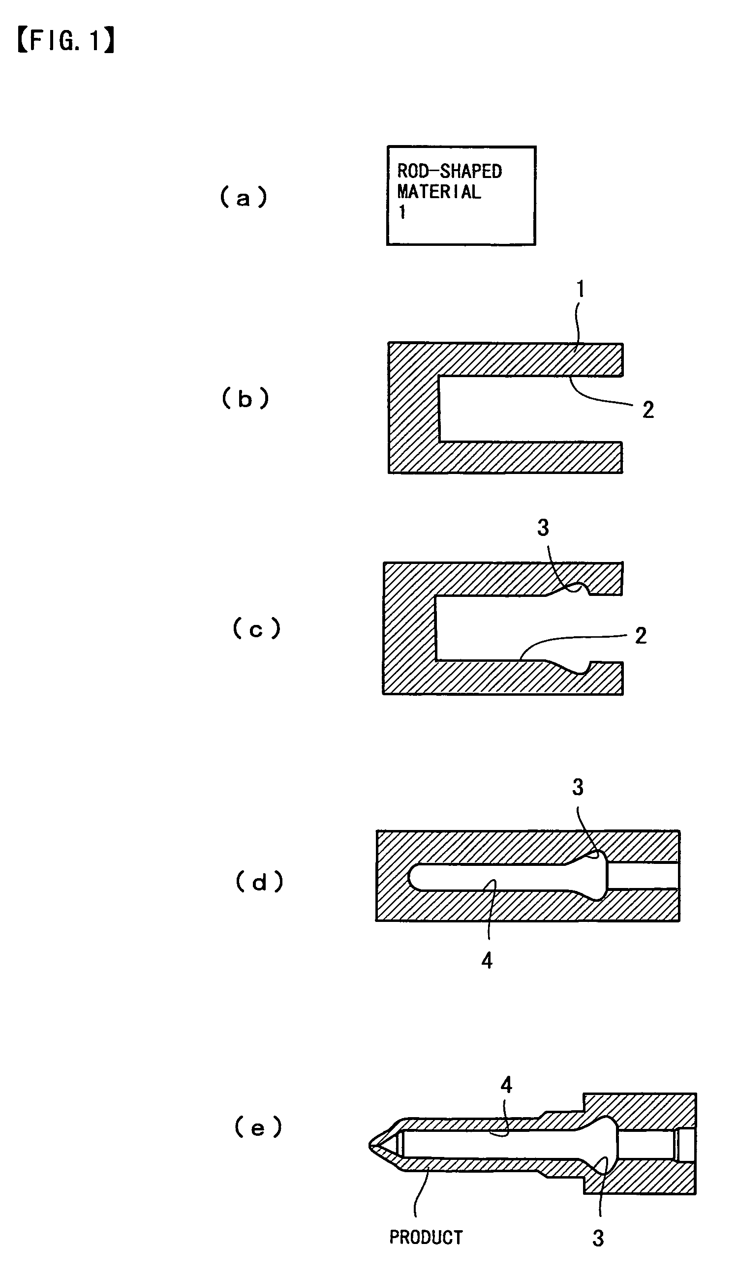
[0073]First, a rod-shaped material 1 is prepared by cutting a billet shown in FIG. 1(a). As this rod-shaped material, SCM415 etc. are suitable.

[0074]Subsequently, as shown in FIG. 1 (b), a recess 2 is formed in the rod-shaped material 1 by cold forging (forward extrusion or backward extrusion). This recess 2 is a portion that forms the inner peripheral portion of product subsequently. The recess 2 is formed so as to have a diameter larger than that of the inner peripheral portion of product and have a diameter so large that the recess 2 can be machined satisfactorily (not smaller than 10 mm).

[0075]Next, as shown in FIG. 1(c), an undercut 3 is formed in the recess 2, and successively, as shown in FIG. 1(d), the recess 2 is formed into a blind hole 4 having an inside diameter of 2 to 4 mm by cold swaging. Further, the outer peripheral surface is machined by turning to obtain a prod...


PUM

PropertyMeasurementUnit
diameteraaaaaaaaaa
diameteraaaaaaaaaa
diameteraaaaaaaaaa

Abstract

There is provided a method by which a member having an undercut in the inner peripheral portion thereof can be formed readily. To form a material (1) formed with a recess (2) and the undercut (3) by using a swaging device, while the material (1) is first gripped by a damper (11), and a mandrel (12) is inserted into the recess (2) of the material (1). The mandrel (12) used has an outside diameter equal to the inside diameter of a blind hole of an aimed product (fuel injection nozzle). Then, the material (1) is pushed in by the mandrel (12) to a position at which the material (1) abuts on a stopper (13), and the outside surface of the material (1) is struck by swaging dies (8) to perform a swaging operation. This swaging operation reduces the inside diameter of the recess (2) to the outside diameter of the mandrel (12), with the undercut (3) left.

Description

TECHNICAL FIELD[0001]The present invention relates to a method of forming a member having an undercut in a part of the inner periphery thereof, such as a fuel injection nozzle, a valve guide for slidingly guiding a valve system for an automotive engine and a method of forming the valve guide, and a method of forming a tubular member.BACKGROUND ART[0002]A general shape of a fuel injection nozzle is shown in FIG. 26. The fuel injection nozzle is formed with a hollow hole with an inside diameter of 2 to 4 mm in the axial direction. A fuel jet is formed at the tip end of the hollow hole, and an undercut serving as a fuel reservoir is formed in a far portion of the hollow hole.[0003]It is when the diameter of the inner peripheral portion of the member is 10 mm at the smallest that the undercut can be formed by machining in the inside portion of the member. In order to form the undercut in the inner peripheral portion of the hollow hole with an inside diameter of 2 to 3 mm as in the case ...

Claims


Application Information

Patent Timeline
Patent Type & Authority Applications(United States)
IPC IPC(8): B23P13/02B21C23/14B21J7/14B21J7/16B21K1/20B21K21/08F02M61/16
CPCB21C23/14B21J7/14B21J7/16B21K1/20B21K21/08F02M61/168Y10T29/49995F02M2200/9038F02M2200/9046F02M2200/9053F02M2200/9076Y10T29/493Y10T29/49996F02M2200/9007B21J5/06
Inventor OHNUMA, TAKAYUKIKOBAYASHI, TAKASHIANDO, TSUTOMUHIRUMA, HIDETAKATAKADA, RYOTARO
Owner HONDA MOTOR CO LTD
Why Eureka
Try Eureka