Triple Cycle Power Plant

a power plant and triple cycle technology, applied in steam engine plants, machines/engines, mechanical equipment, etc., can solve the problems of reducing output, affecting the efficiency of power generation, so as to improve the power output, increase the mass flow of inlet air, and improve the effect of thermal and energy efficiency

Inactive Publication Date: 2008-02-14
FLUOR TECH CORP
View PDF13 Cites 83 Cited by
  • Summary
  • Abstract
  • Description
  • Claims
  • Application Information

AI Technical Summary

Benefits of technology

[0005] The present invention is directed to a power plant configuration and methods in which inlet air chilling is expanded and heat integrated with a combined cycle power plant. In especially preferred aspects, duct firing in the HRSG is increased as a function of increased mass flow of the inlet air due to the expanded inlet air chilling to thereby substantially improve power output. The rejected heat from the inlet air may further be provided to the HRSG to increase the thermal and energy efficiency associated with the use of inlet chilling in a CTG.

Problems solved by technology

This output reduction is a major financial drawback of the simple Brayton cycle or combined cycle power plant, as the power demand is high in summer.
While the inlet cooling of the '695 patent has various advantages, certain difficulties nevertheless remain.
Among other things, Ranasinghe's system is typically limited to Kalina bottoming cycle configurations.
While thermal efficiency of the '563 process is typically improved, components, maintenance, and operation of such cooling systems are generally cost-prohibitive when compared to the overall capital gain.
Therefore, while numerous configurations and processes for power plants are known in the art, all or almost all of them, suffer from one or more disadvantage.

Method used


Image

  • Triple Cycle Power Plant
  • Triple Cycle Power Plant

Examples


example

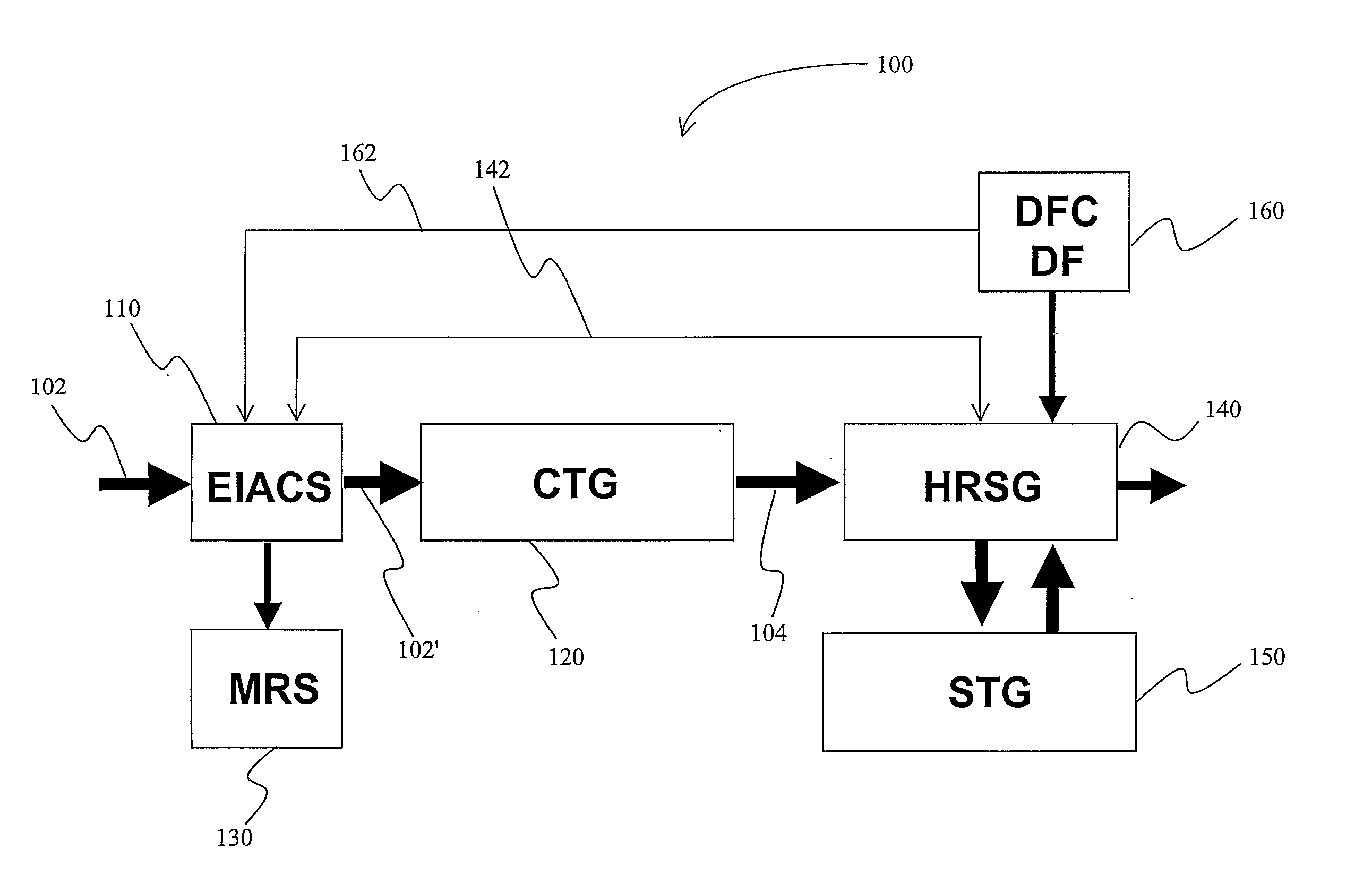
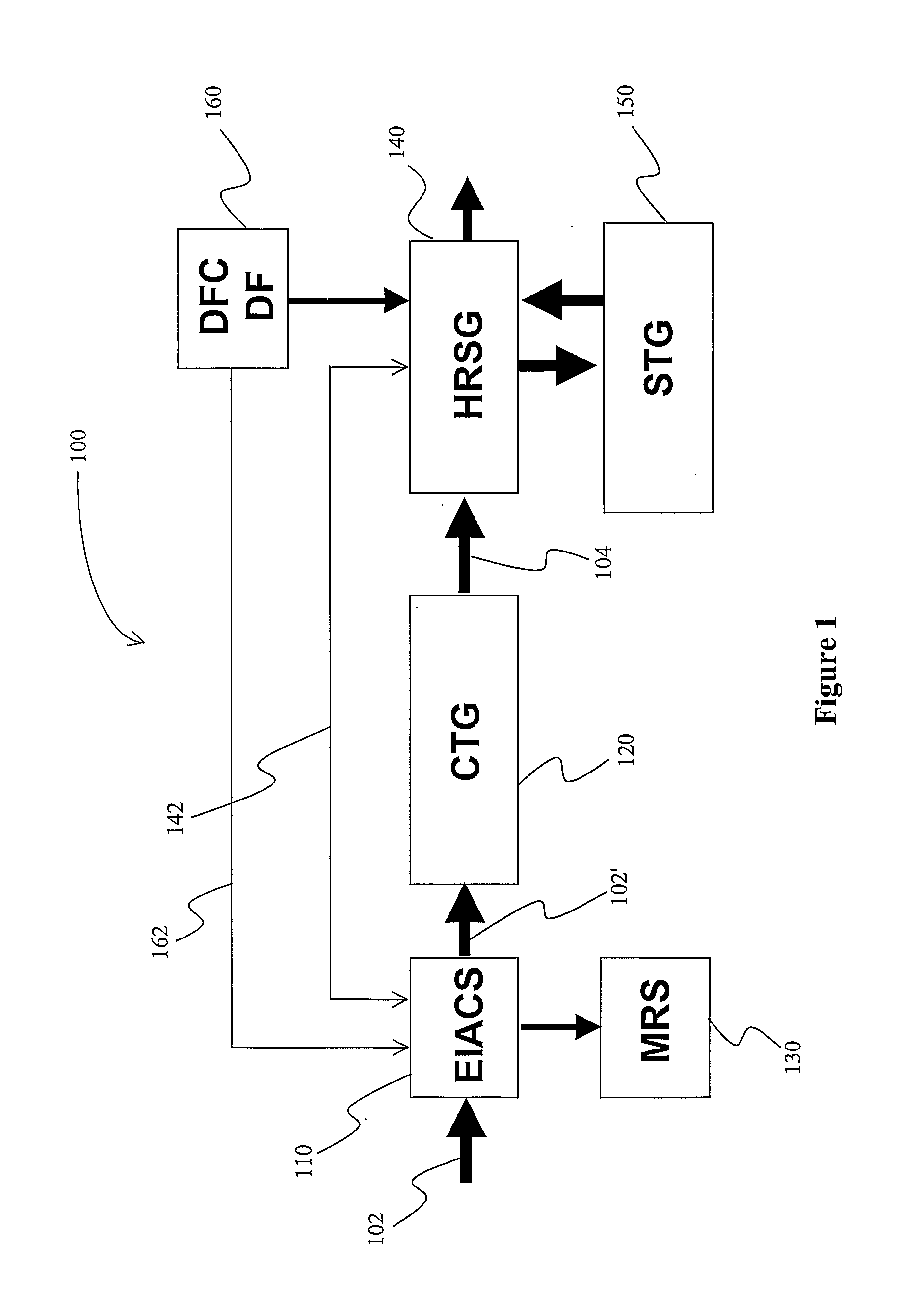
[0023] The following example for a triple cycle configuration was based on a combined cycle (CC) power plant employing two GE 7FA combustion turbine generators (CTG's) and one GE D11-type steam turbine generator (STG) with HRSG duct firing. An expanded inlet air chilling system (EIACS) was configured to chill the combustion turbine inlet air to −10° F. A TEG-based moisture removal system (MRS) was added to avoid icing at the compressor inlet. Heat integration was further based on both, high CTG exhaust mass flow (and with that increased duct firing) and use of rejected heat from the EIACS.

[0024] The performance of the EIACS and the MRS were evaluated with HYSYS models developed to simulate the selected configurations. Other published design data were also used where applicable. GT-PRO / MASTER was used to analyze the benefits of heat integration schemes. All evaluations are based on preliminary specifications of design parameters, and it should be appreciated that the performance and...


PUM


Abstract

Abstract: A refrigeration cycle is integrated into a combined cycle power plant to form a triple cycle power plant in which gas turbine generator inlet air is chilled and dehydrated to increase the mass flow of the inlet air, and in which duct firing in HRSG is increased in dependence of the increased mass flow. In further preferred integration aspects, the heat from the inlet chiller refrigerant is provided to the HRSG.

Description

FIELD OF THE INVENTION [0001] Configurations and methods for combined cycle power plants. BACKGROUND OF THE INVENTION [0002] In a typical Brayton cycle, the output from the combustion turbine generator (CTG) becomes significantly less at high ambient temperatures. This output reduction is a major financial drawback of the simple Brayton cycle or combined cycle power plant, as the power demand is high in summer. Inlet air cooling for open Brayton cycle configurations to increase net power output is well known in the art. However, in many cases the temperature of the inlet air must be kept above the dew point of the inlet air to avoid condensation, or even freezing out of the water contained in the inlet air. To avoid at least some of the problems associated with condensation during cooling, numerous improved configurations have been developed. For example, a freezing point depressant (which may also absorb water) may be sprayed onto the heat exchanger as described in U.S. Pat. No. 3,...

Claims


Application Information

Patent Timeline
Patent Type & Authority Applications(United States)
IPC IPC(8): F02C6/00F01K23/10F02C6/18F02C7/143
CPCF01K23/105Y02E20/16F02C7/143F02C6/18
Inventor SUTIKNO, TEK
Owner FLUOR TECH CORP
Why Eureka
Try Eureka