[0020](1) A substrate treatment apparatus according to the present invention includes a box-shaped treatment bath having an opening part at its upper side, and a cover body openably covering the opening part of the treatment bath. The cover body includes a drying chamber formed therein for storing and drying a substrate to be treated. The treatment bath is so formed that at least three of treatment liquid supply
nozzle tubes are disposed at each of the opposed side wall faces thereof forming the box shape horizontally at specified intervals and these supply nozzle tubes are formed to be connected to a switching mechanism to supply a treatment liquid from the opposed side wall sides while alternately switching them at the opposed side wall faces.
[0027]For example, after the completion of the treatment of a specified chemical liquid A, the supply of the chemical liquid is stopped and by supplying pure water only from three supply nozzle tubes provided on any one of the opposed side wall faces, the chemical liquid A is purged for a specified time. Consequently, the supply of pure water from the three supply nozzle tubes from which pure water has been supplied first is stopped and by supplying pure water from three supply nozzle tubes provided on the other of the opposed side wall faces, the flow of the liquid in the bath is gradually changed to purge the chemical liquid A which has been settled in the bath and could not be purged. Further, by supplying pure water from all of the supply nozzle tubes to increase the flow amount and flow rate of pure water, the substrate to be treated and the inside of the bath can be cleaned in a short time. This is because the direction of the supplying of pure water is changed at a stretch, but the flow rate is changed not at a stretch but gradually, so that the settlement caused first is gradually moved and the remained chemical liquid can be swiftly purged. By performing the same treatment and cleaning in the treatment with the chemical liquid B as those in the treatment with the chemical liquid A and by repeating such treatment and cleaning, the exchange of the chemical liquid and cleaning liquid is speeded up and a series of treatments including the treatment of chemical liquids, flushing and drying can be performed in the same treatment bath.
[0028]Since between a supply nozzle tube for supplying both a chemical liquid and pure water and a treatment liquid supply source, a mixing device which makes the concentration of the treatment liquid to a specified concentration is connected and treatment liquids are supplied from the mixing device into the bath, a large amount of pure water cannot be supplied from such a supply nozzle tube during the exchange of the treatment liquids. However, according to the present invention, by providing supply nozzle tubes used exclusively for pure water, pure water can be supplied not through the mixing device into the bath. In addition by supplying pure water also from other supply nozzle tubes, a large amount of pure water is supplied into the bath in a short time. With the large amount of pure water, the substrate to be treated and the inside of the bath can be cleaned.
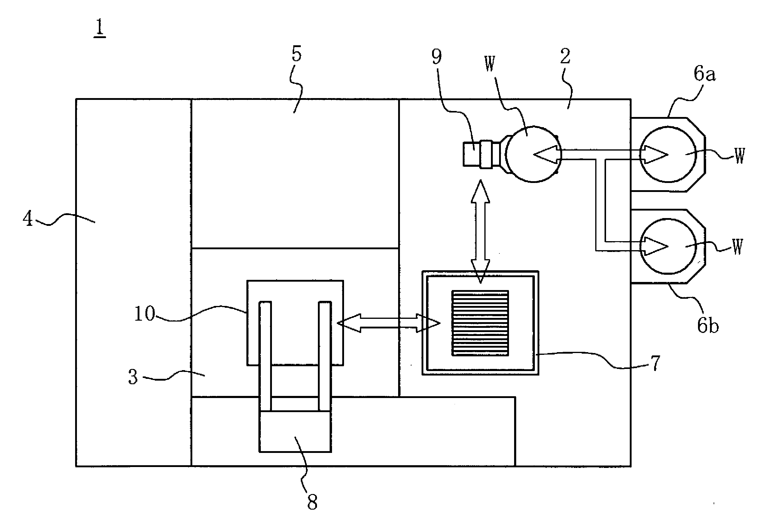
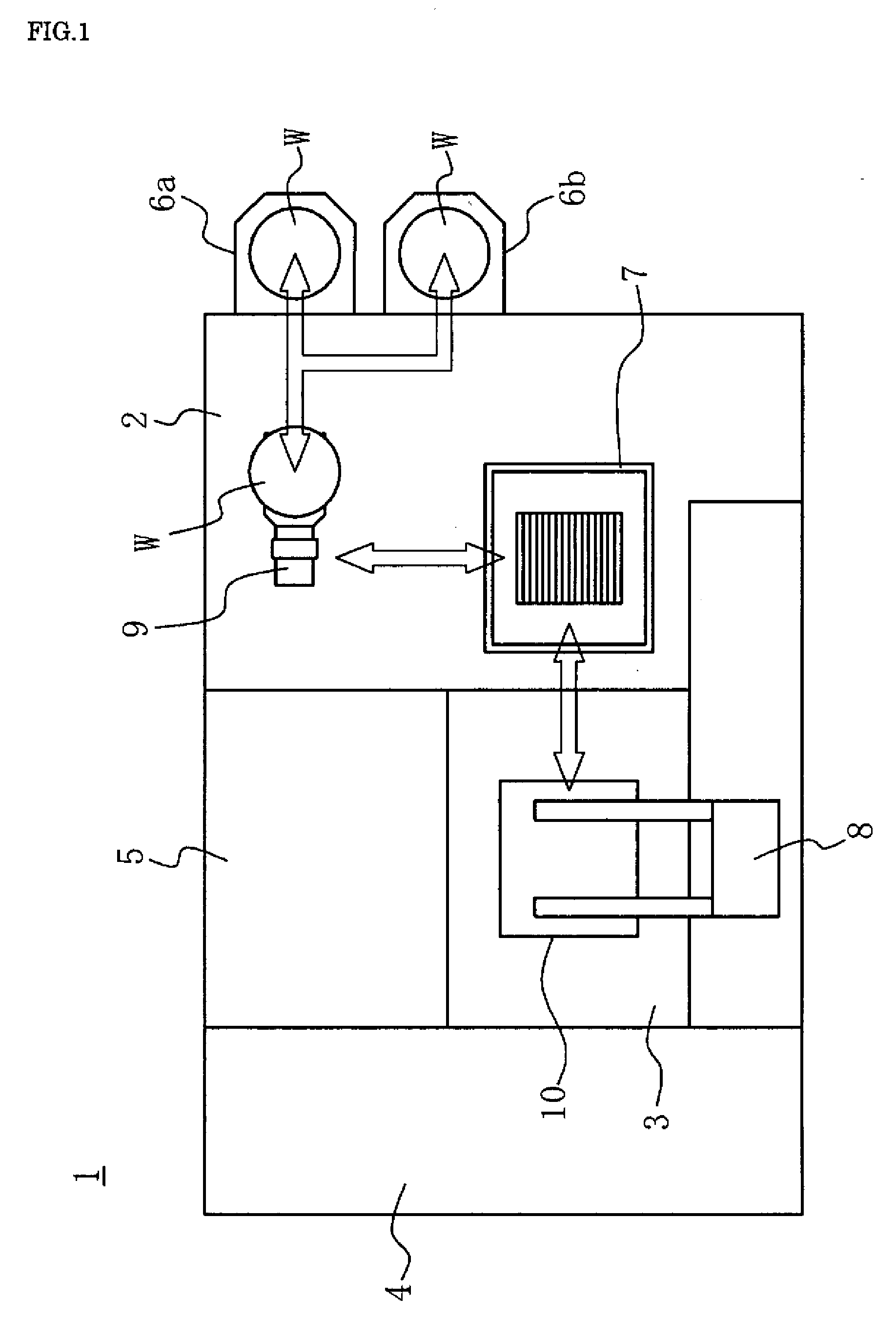
[0029]Since the cover body covers openably the opening part of the treatment bath and in the inside thereof, the drying chamber is formed, the cover body can be moved upward or in the side direction from the opening part during the treatment of the substrate, so that the
contamination of the cover body by the chemical liquid can be avoided. Further, since during the drying, the opening part of the treatment bath is covered by the cover body and the substrate to be treated is pulled up from the treatment bath and is dried in the drying chamber, the substrate is not exposed to air during the moving thereof, so that the generation of an
oxide film on the surface of the substrate is prevented and high quality drying can be performed.
[0030]According to a preferred aspect of the present invention, by providing supply nozzle tubes used exclusively for pure water, pure water can be supplied efficiently.
[0031]Since between a supply nozzle tube for supplying both a chemical liquid and pure water and a treatment liquid supply source, a mixing device which makes the concentration of the treatment liquid to a specified concentration is connected and treatment liquids are supplied from the mixing device into the bath, a large amount of pure water cannot be supplied from such a supply nozzle tube during the exchange of the treatment liquids. However, according to the present invention, by providing supply nozzle tubes used exclusively for pure water, pure water can be supplied not through the mixing device and consequently in a large amount into the bath. In addition by supplying pure water also from other supply nozzle tubes, a large amount of pure water is supplied into the bath in a short time. With the large amount of pure water, the wafer and the inside of the bath can be rapidly cleaned.
[0032]According to another preferred aspect of the present invention, by using a supply nozzle tube having a simple structure, pure water or a chemical liquid can be efficiently supplied to the substrate to be treated. Moreover since the flow amount can be increased in the bath and a flow in a specified direction which has a large flow rate can be formed, not only the settlement of the cleaning liquid in the bath can be prevented, but also the replacing efficiency can be improved.
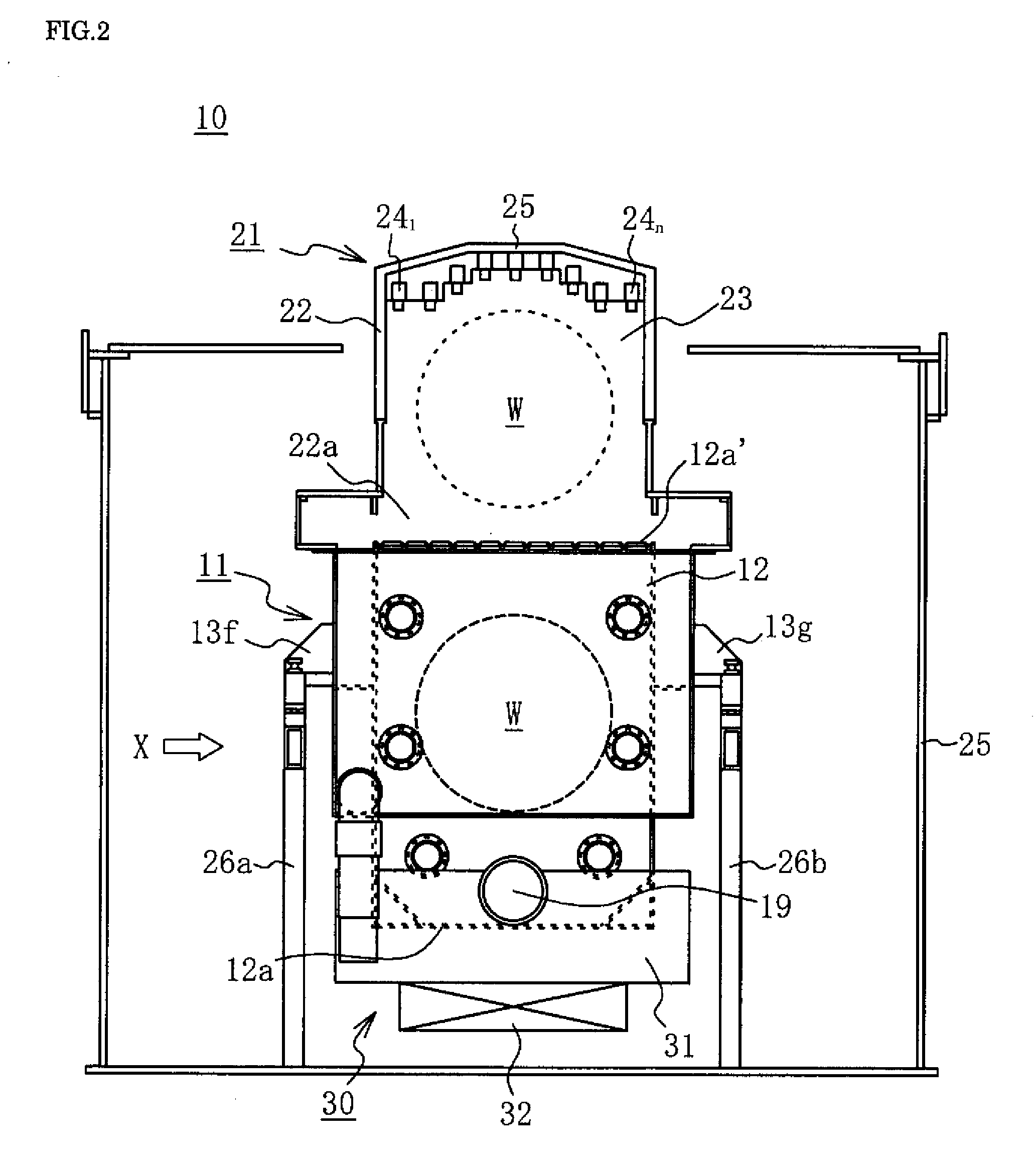
[0033]According to still another preferred aspect of the present invention, since the bottom wall is inclined from the horizontal direction by a specified angle, the permeability of the ultrasonic is improved. Furthermore, since a
discharge outlet is formed at a lower end of the bottom wall, the
sediment accumulated on the bottom of the bath slides down along the inclined bottom wall surface and can be easily discharged out of the
discharge outlet. Therefore, each time when the treatment liquid is exchanged, the
sediment on the bottom of the bath is discharged out of the bath, so that it is possible to keep the bath clean.
[0034]According to still another preferred aspect of the present invention, the substrate to be treated can be subjected to not only a
chemical treatment with a treatment liquid, but also to a physical treatment by an
ultrasonic vibration, and by a combination of these treatments, a high quality treatment can be performed.
[0035]According to still another preferred aspect of the present invention, a
dry gas containing submicron
organic solvent mist is supplied from a dry vapor supply device into the drying chamber. Therefore, since mist contained in the
organic solvent vapor is submicron in size, the number of mist particles of the
organic solvent can be large without increasing the amount of the organic
solvent. Further, while the surface area of an individual mist particle is small, in line with the large number of mist particles, the total surface area of mist particles, which is a total sum of the surface area of an individual mist particle, is large. As a result, a large amount of submicron mist particles can be injected to the surface of the substrate, so that a cleaning liquid attached to the substrate can be efficiently replaced by the large amount of submicron organic
solvent mist particles. Moreover, even when a large number of substrates having a large
diameter are inserted into the treatment bath, since a plurality of injection nozzles are disposed, and consequently submicron mist particles can rapidly intrude between the substrates, not only the efficiency of the drying can be improved, but also the
treatment time can be shortened. Accordingly, the cause of a water mark on the
substrate surface can be reduced to extremely little or almost nothing. Further, the attaching of particles to the substrate can be prevented, and moreover the speed of the drying is enhanced, so that the reattaching of particles can be also prevented.

