Bonded nonwoven fibrous webs comprising softenable oriented semicrystalline polymeric fibers and apparatus and methods for preparing such webs

Active Publication Date: 2008-02-14
3M INNOVATIVE PROPERTIES CO
View PDF18 Cites 264 Cited by
  • Summary
  • Abstract
  • Description
  • Claims
  • Application Information

AI Technical Summary

Benefits of technology

[0074]Another important advantage of the invention is the ability to shape a web of the invention. By shaping it is meant reconfiguring the web into a persistent new configuration, i.e., a self-sustaining configuration that the web will generally retain during use. In some cases shaping means smoothing one or both surfaces of the web and in some cases compacting the web. In other cases shaping involves configuring the web into a nonplanar shape such as perhaps a cup-shape for use in a face mask. Again the fibrous character of the web is retained during shaping, though the fibers may receive a somewhat different cross-section through the pressure of the shaping operation.
[0075]Besides improved bondability and shapability, fibers of the invention can provide other useful properties and features. For example, the improved morphological purity of the fibers as found in the amorphous-characterized phase may make the fibers chemically more reactive, enhancing use of the fiber for such purposes as grafting substrates. The fact that a web of the invention can be bonded without addition of an extraneous material is another important advantage, enhancing utility of the webs as membrane supports, electrochemical cell separators, filtration media, etc.
[0076]The invention is further illustrated in the following illustrative examples. Several examples are identified as comparative examples, because they do not show certain properties (such as softening, bonding, or DSC characteristics) desired for bondability, moldability, etc.; but the comparative examples may be useful for other purposes and may exhibit novel and nonobvious character.
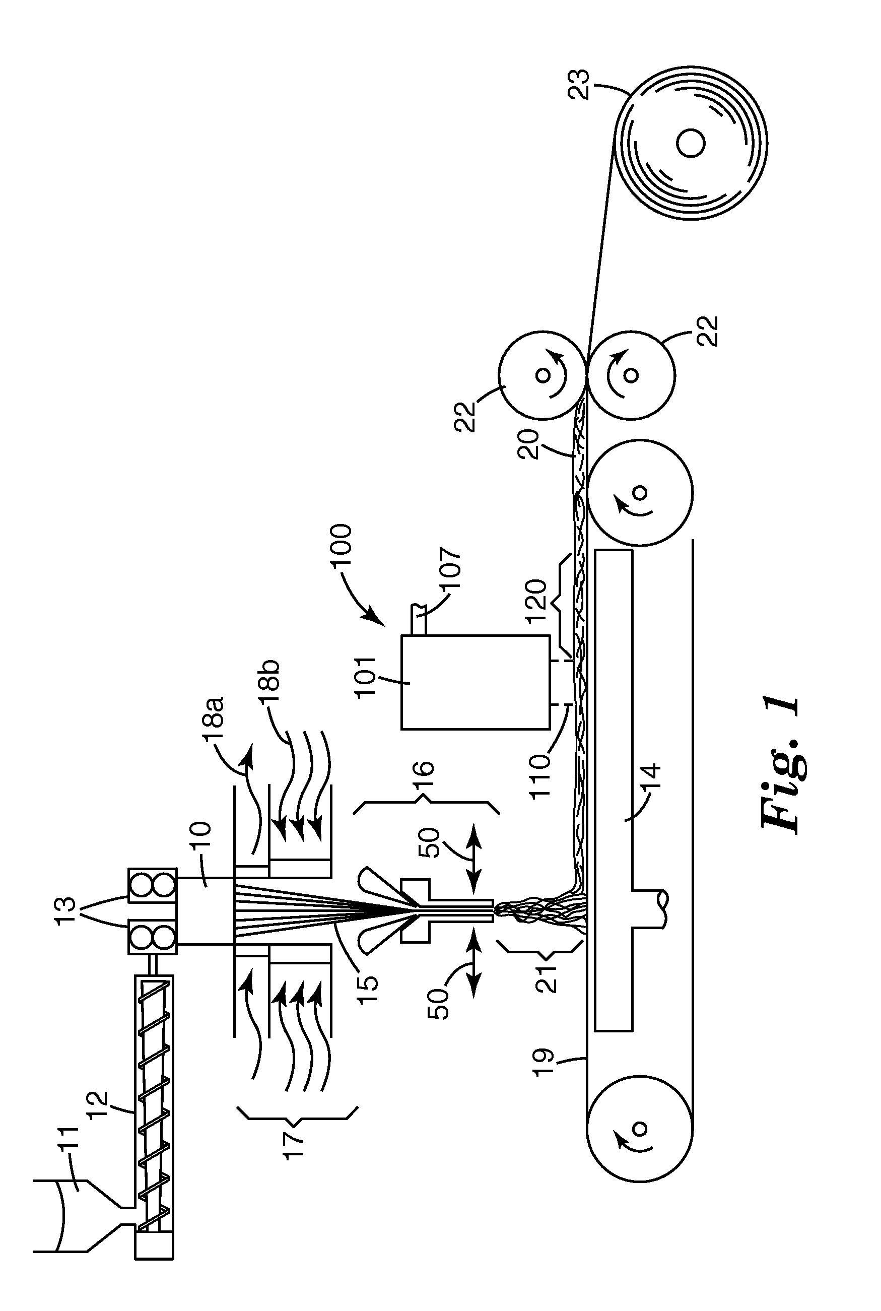
[0077]Apparatus as shown in FIGS. 1-5 was used to prepare fibrous webs from polypropylene and polyethylene terephthalate. Examples 1-3 and C1-C6 were prepared from polypropylene (PP) having a Nominal Melting Point of 160.5° C. and a melt flow index (MFI) of 70 (Dypro 3860× polypropylene resin supplied by Total Chemical of Houston, Tex.). Examples 4-6 and C7-C8 were prepared from polyethylene terephthalate (PET) having a Nominal Melting Point of 254.1° C. and an intrinsic viscosity of 0.61 (3M Polyester Resin 65100).
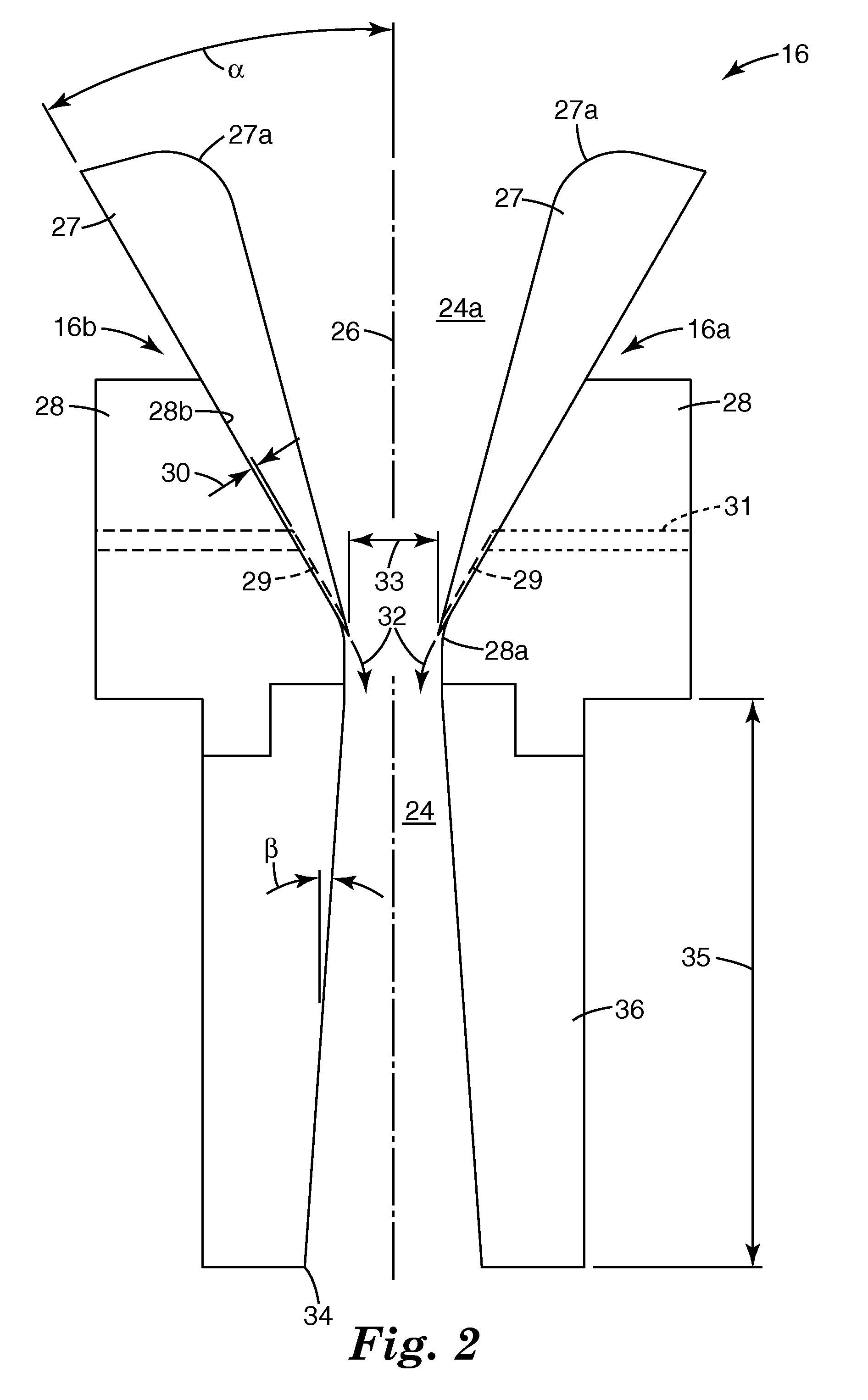
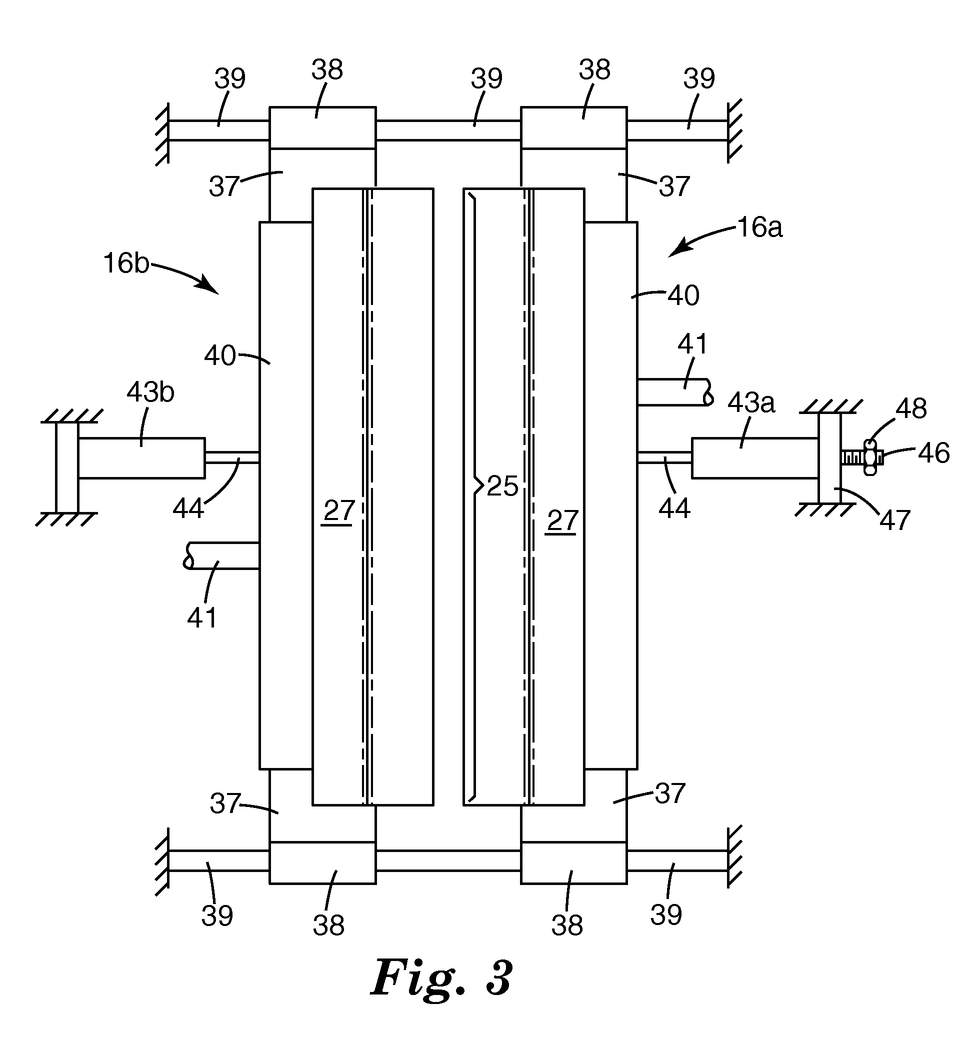
[0078]Certain parts of the apparatus and operating conditions are summarized in Table 1. The clamping pressure reported in the table was sufficient that the walls of the attenuator remained generally fixed during pre

Problems solved by technology

The result of the increased lower-order crystallinity is to limit

Method used


Image

  • Bonded nonwoven fibrous webs comprising softenable oriented semicrystalline polymeric fibers and apparatus and methods for preparing such webs
  • Bonded nonwoven fibrous webs comprising softenable oriented semicrystalline polymeric fibers and apparatus and methods for preparing such webs
  • Bonded nonwoven fibrous webs comprising softenable oriented semicrystalline polymeric fibers and apparatus and methods for preparing such webs

Examples


Example

[0081]FIG. 9 shows three nonreversing heat flow plots obtained for the webs of Examples C1, 1 and C6, each web having been subjected to heat treatment at a different temperature—Example C1, about 151° C. (Plot A), Example 1, about 154° C. (Plot B), and Example C6, about 166° C. (Plot C). Example C1 was treated at a temperature too low to accomplish a desired morphological refinement according to the invention, and Plot A shows that because there is a significant crystal-perfection peak TCP having its greatest magnitude at a temperature lower than the Nominal Melting Point. Example 1 was treated at an effective temperature, and Plot B shows that the greatest magnitude of the crystal-perfection peak is above the Nominal Melting Point. Example C6 was treated at too high a temperature to accomplish a desired morphological reduction (note that a significant crystal-perfection peak has been regenerated at a temperature lower than the Nominal Melting Point; in other words, the heat treatme...

Example

[0084]The molding capabilities of the webs of Examples 4 and C8 were examined by molding representative samples into a respirator-shaped cup shape using conventional molding conditions but different mold temperatures shown in Table 2 below. Two samples of each example were molded using a five-second molding cycle. The mold height was 5.7 centimeters and formed a generally oval shape with a minor axis of 11.5 centimeters and 13 major axis. There was a 0.5-centimeter gap between mold sections. The height of the molded cup was measured by clamping it to a table top, placing a flat blade on top of the molded cup, and measuring the distance from the table top to the knife blade. A 100-gram weight was then laid on the blade and the height measured again. Table 2 reports the mold temperatures and the height measurements.

TABLE IExample No.C1C212C3C4C5PolymerPPPPPPPPPPPPPPMFI / IV70707070707070Melt(° C.)235235235235235235235TempPolymer(g / orifice / 0.60.60.20.20.20.20.2Flow Ratemin)Die to(cm)8484...

Example

[0085]As will be noted, the webs of Example 1 replicated well the mold shape even when molded at a temperature of 155° C., less than the Nominal Melting Point of the webs. All the molded Example 1 webs except one of those molded at 155° C. and the two molded at 205° C. were essentially at mold height and the others were at least 87% or 83%, respectively, of mold height. (For purposes herein replication is regarded as attaining at least 75% of mold dimensions.) It is also noted that the molded Example 1 webs held their shape well under pressure, while the C8 molded webs essentially collapsed under pressure.

EXAMPLES 7-8

[0086]The webs of Examples 7 and 8 and C9-C11 were prepared by carding oriented crimped nylon 6-6 staple fibers on a Holingsworth random card; the fibers, supplied by Rhodia Technical Fibers, Gerliswilstrasse 19 CH-6021 Emmenbrucke, Germany, were characterized as 2-inch (about 5 centimeter) cut staple 6-denier (16.7 decitex) fiber having a crimp count of three per inch...


PUM

PropertyMeasurementUnit
Temperatureaaaaaaaaaa
Thicknessaaaaaaaaaa
Angleaaaaaaaaaa

Abstract

A method for making a bonded nonwoven fibrous web comprising 1) providing a nonwoven fibrous web that comprises oriented semicrystalline polymeric fibers, and 2) subjecting the web to a controlled heating and quenching operation that includes a) forcefully passing through the web a fluid heated to at least the onset melting temperature of said polymeric material for a time too short to wholly melt the fibers, and b) immediately quenching the web by forcefully passing through the web a fluid at a temperature at least 50° C. less than the Nominal Melting Point of the material of the fibers. The fibers of the treated web generally have i) an amorphous-characterized phase that exhibits repeatable softening (making the fibers softenable) and ii) a crystallite-characterized phase that reinforces the fiber structure during softening of the amorphous-characterized phase, whereby the fibers may be autogenously bonded while retaining orientation and fiber structure. Apparatus for carrying out the method can comprise 1) a conveyor for conveying a web to be treated, 2) a heater mounted adjacent a first side of the conveyor and comprising a) a chamber having a wall that faces the web, b) one or more conduits through which a heated gas can be introduced into the chamber under pressure and c) a slot in said chamber wall through which heated gas flows from the chamber onto a web on the conveyor, 3) a source of quenching gas downweb from the heater on the first side of the conveyor, the quenching gas having a temperature substantially less than that of the heated gas, 4) gas-withdrawal mean disposed on the second side of the conveyor opposite from the heater, the gas-withdrawal means having a portion in alignment with the slot so as to draw heated gas from the slot through the web and also a portion downweb from the slot in alignment with the source of quenching gas so as to draw the quenching gas through the web to quench the web. Flow restrictor means is preferably disposed on the second side of the conveyor in the path of at least one of the heated gas and the quenching gas so as to even the distribution of the gas through the web.

Description

FIELD OF THE INVENTION[0001]This invention relates to fibrous webs that comprise oriented semicrystalline polymeric fibers having unique softening characteristics that provide the webs with enhanced bonding and shaping properties; and the invention further relates to apparatus and methods for preparing such webs.BACKGROUND OF THE INVENTION[0002]Existing methods for bonding oriented semicrystalline polymeric fibers in a nonwoven fibrous web generally involve some compromise of web properties. For example, bonding of the web may be achieved by calendering the web while it is heated, thereby distorting fiber shape and possibly detracting from other properties such as web porosity or fiber strength. Or bonding may require addition of an extraneous bonding material, with consequent limitations on utility of the web because of the chemical or physical nature of the added bonding material.SUMMARY OF THE INVENTION[0003]The present invention provides new nonwoven fibrous webs comprising orie...

Claims


Application Information

Patent Timeline
IPC IPC(8): B32B5/24B32B3/26
CPCD04H3/16D04H3/00Y10T428/2481Y10T428/2913Y10T428/2969Y10T428/249953Y10T442/3325Y10T442/60Y10T442/614Y10T442/619Y10T442/626Y10T442/641Y10T442/68Y10T442/69D04H3/08D04H17/00
Inventor BERRIGAN, MICHAEL R.STELTER, JOHN D.PERCHA, PAMELA A.FOX, ANDREW R.FAY, WILLIAM T.
Owner 3M INNOVATIVE PROPERTIES CO
Why Eureka
Try Eureka