Method of correcting message errors using cyclic redundancy checks

a message error and redundancy check technology, applied in error detection only, coding, code conversion, etc., can solve the problems of request for a retransmission of the message, lack of sparse parity check matrix, computational complexity, etc., to improve the performance of message passing decoding and reduce the packet error rate of the communication channel

Active Publication Date: 2008-02-14
ACLARA TECH LLC
View PDF11 Cites 8 Cited by
  • Summary
  • Abstract
  • Description
  • Claims
  • Application Information

AI Technical Summary

Benefits of technology

[0008]The present invention is directed to a method of correcting errors in a message of a fixed length that includes CRC parity check bits for error detection. The method includes generating a parity check matrix representation of the CRC which can be applied to any type of CRC regardless of its size or generator polynomial. If a message is also encoded with a block error correcting code such as a Hamming, BCH, Reed-Muller, or Reed-Solomon code, the parity-check matrix is combined with the parity check matrix for the error correcting code to comprise a single parity-check matrix. Because the resulting matrix is not expected to be a sparse matrix, sparsification techniques are utilized to improve its performance for message passing decoding. The result is a reduction in the packet error rate of the communications channel.

Problems solved by technology

However, most commonly used block codes, such as Hamming, BCH, and Reed-Solomon codes, do not have sparse parity check matrices.
Using these sparsification methods, it has been shown that improved performance can be achieved with these older classes of codes; although this comes at the cost of computational complexity, and the performance does not surpass that of good LDPC codes.
Depending upon the application, a detected error often results in a request for a retransmission of the message.
Conversely, some communications are quite noisy and error prone, and retransmissions are commonplace.
In practice, however, it is theoretically possible for some errors to go undetected.

Method used


Image

  • Method of correcting message errors using cyclic redundancy checks
  • Method of correcting message errors using cyclic redundancy checks
  • Method of correcting message errors using cyclic redundancy checks

Examples


Embodiment Construction

[0015]The following detailed description illustrates the invention by way of example and not by way of limitation. This description will clearly enable one skilled in the art to make and use the invention, and describes several embodiments, adaptations, variations, alternatives and uses of the invention, including what I presently believe is the best mode of carrying out the invention. As various changes could be made in the above constructions without departing from the scope of the invention, it is intended that all matter contained in the above description or shown in the accompanying drawings shall be interpreted as illustrative and not in a limiting sense.

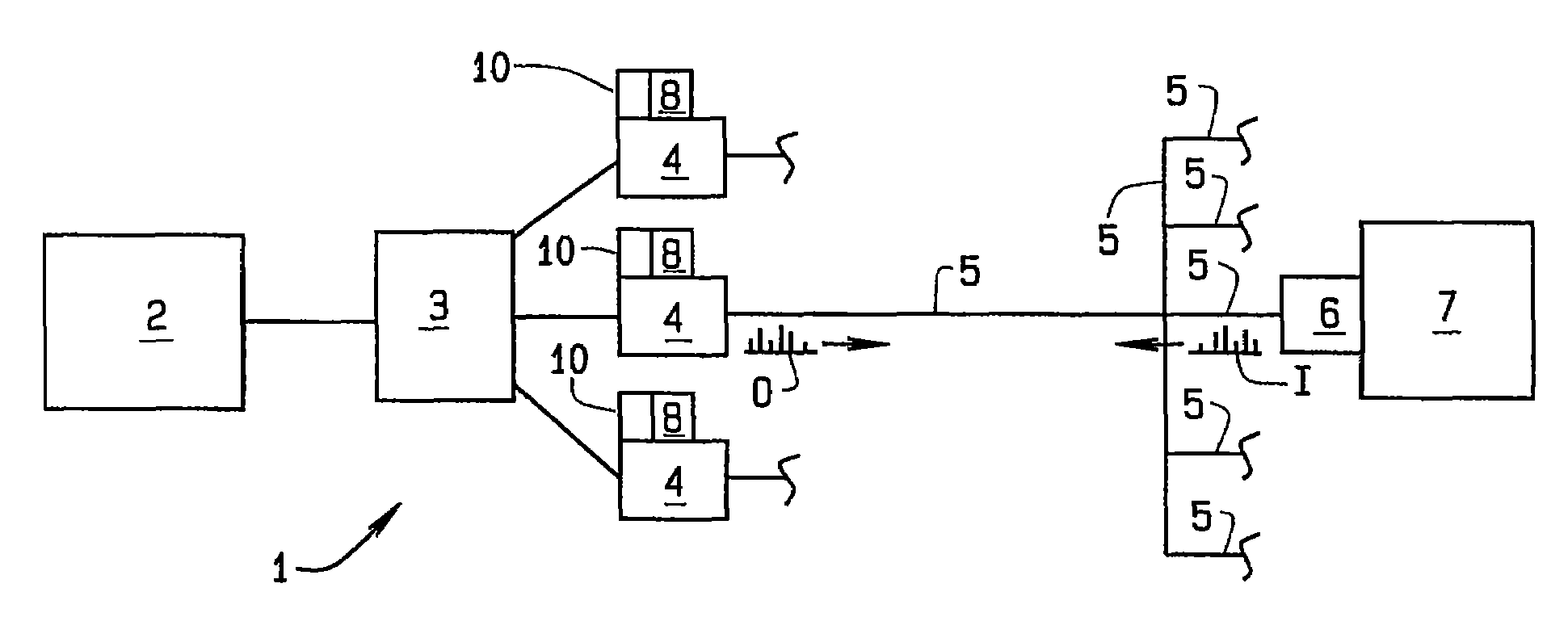
[0016]Traditionally, a CRC has been implemented using a linear feedback shift register (LFSR) such as the 16 bit register R shown in FIG. 1. This is because of the shift register's very low cost when implemented in hardware. However, the serial nature of the register is not sufficiently fast for some applications. As is known ...


PUM


Abstract

A method of correcting errors in a message transmitted over a digital communication channel, where the message was encoded using a CRC for purposes of error detection. A parity-check matrix representation of the CRC is computed for any fixed-length message, and that parity-check matrix is combined with the parity-check matrix for any error correcting code that used in conjunction with the CRC. The combined parity-check matrix is extended using sparsification algorithms to allow it to work well under a message passing decoder (MPD). Received messages are decoded using the message passing decoder, making it possible to correct more errors than if the CRC were decoded in a conventional manner.

Description

CROSS-REFERENCE TO RELATED APPLICATIONS[0001]The present application is related to and claims priority from U.S. Provisional Patent Application Ser. No. 60 / 837,349 filed on Aug. 11, 2006, which is herein incorporated by reference.STATEMENT REGARDING FEDERALLY SPONSORED RESEARCH[0002]Not Applicable.BACKGROUND OF THE INVENTION[0003]This invention relates to a method of error detection and correction in messages sent over a digital communications channel. Specifically, the method uses cyclic redundancy checks (CRCs), which previously have only been used for error detection, to provide a certain amount of correction in messages where errors are detected. One practical application of the method described herein relates to error detection in messages sent over a power distribution system employing a TWACS® communication system to send and receive messages over electrical power lines to acquire information on the status of power users, including current power usage. In particular, the meth...

Claims


Application Information

Patent Timeline
Patent Type & Authority Applications(United States)
IPC IPC(8): H03M13/05
CPCH03M13/1111H03M13/09
Inventor SPENCER, QUENTIN
Owner ACLARA TECH LLC
Why Eureka
Try Eureka