Selective heating in adsorbent systems

a technology of adsorbent system and selective heating, which is applied in the direction of machine/engine, mechanical equipment, separation processes, etc., can solve the problems of reducing recovery capacity, and reducing useful service life, so as to achieve efficient improvement of working capacity and useful service life

Inactive Publication Date: 2008-02-21
HILTZIK LAURENCE H +3
View PDF40 Cites 56 Cited by
  • Summary
  • Abstract
  • Description
  • Claims
  • Application Information

AI Technical Summary

Benefits of technology

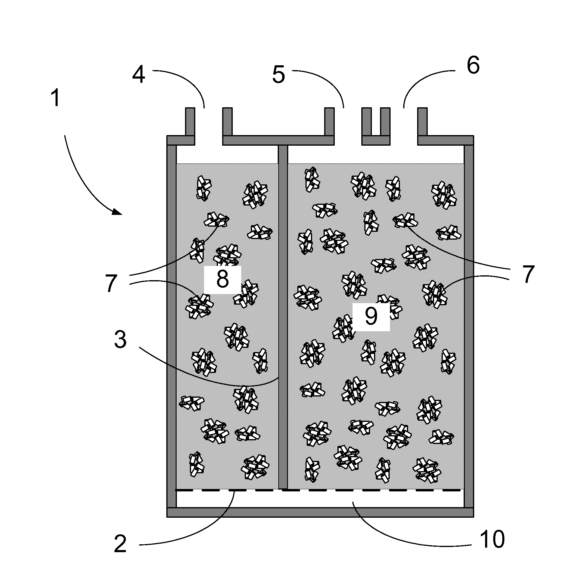
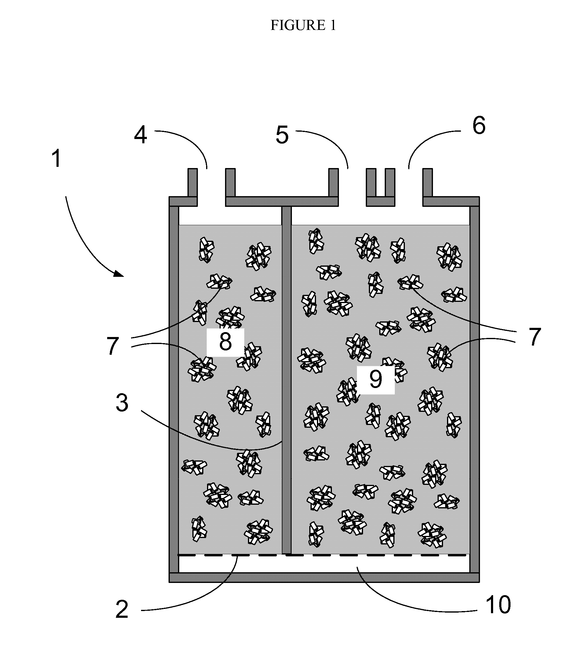
[0013] An invention is disclosed for efficiently improving the working capacity and useful service life of an adsorbent system by selectively heating the adsorbent towards the purge outlet of the fluid flow path.

Problems solved by technology

However, the presence of more tenaciously adsorbed compounds and impurities in the fluid streams can lead to a build up of those adsorbates in the adsorbent that usurps recovery capacity, thereby reducing the useful service life.
The reaction products can be difficult to desorb owing to their greater molecular weight, larger size, and lower volatility, thereby lowering recovery capacity over time and reducing useful service life.
Evaporation of gasoline from motor vehicle fuel systems is a major potential source of hydrocarbon air pollution.
Recent designs of vehicle engines for greater fuel efficiency, including combination hybrid electric / combustion engine drive trains and engines where multiple cylinders idle during operation, are challenged to provide for sufficient recovery of vapor emissions and for adequately low emissions because these engine systems do not provide a sufficient volume of purge for adsorbent regeneration.
Therefore, the reduction in purge volume with newer engine designs is counter to maintaining evaporative emission control system performance over years of vehicle usage as mandated by environmental regulations.
For the particular application of adsorbent for control of evaporative fuel emissions from vehicles, extensive study of adsorbent vapor distributions and thermal properties during canister operation revealed that prior methods of heating the purge inlet were inadequate for the extraordinary cycling conditions encountered in newer, purge-deficient engine designs in terms of enhancing adsorbent working capacity and for enhancing the service life of the evaporative emission control system for vapor recovery.
The prior methods of heating along the entire flow path length require undesirably large components and require unnecessarily high power usage in heating the entire adsorbent, which is especially wasteful in light of the discovery that only a portion of the flow path need be heated.

Method used


Image

  • Selective heating in adsorbent systems
  • Selective heating in adsorbent systems
  • Selective heating in adsorbent systems

Examples


example 1

[0055] A canister 201 was fabricated from Plexiglas® (FIGS. 16 and 17) and was equipped with screens 303 for retaining adsorbent, a purge outlet (adsorption step vapor source inlet) port 304 connected to three-way valve 209, a purge inlet (adsorption step exhaust outlet) port 305 connected to three-way valve 208, and activated carbon adsorbents in volumes 307-309 with a cumulative vapor flow path length of 17 cm and volume 310 with a vapor flow path length of 17 cm. The purge outlet section consisted of a 500 cc volume 307 filled by an activated carbon monolith module. Volume 307 encompassed the adsorbent flow path from 83% to 100% of the fractional distance from the purge inlet, or 75-100% of the fractional adsorbent volume from the purge inlet. Volumes 308 and 309 were each filled with 500 cc of 1.6 mm carbon pellets 311 made by phosphoric acid activation according to the method described in U.S. Pat. No. 5,324,703. Volume 308 encompassed the adsorbent flow path from 67% to 83% of...

example 2

[0058] The construction of canister 201 was the same as that described for Example 1, except that the volumes 307 and 309 each contained 500 cc of 1.6 mm activated carbon pellets 311. Volume 308 contained the activated carbon monolith module. The butane loading data after adsorption and after purge and the working capacity data for the Example 2 canister are provided in Table II.

example 3

[0059] The construction of canister 201 was the same as that described for Example 1, except that the volumes 307 and 308 each contained 500 cc of 1.6 mm activated carbon pellets 311. Volume 309 contained the activated carbon monolith module. The butane loading data after adsorption and after purge and the working capacity data for the Example 3 canister are provided in Table III.

TABLE IIIEffectButane Loadingof Heat atPurgeAfterAfterWorkingthe SameHeatedVolumePurgeAdsorbPurgeCapacityPurgeVolumev / vHeatg / Lg / Lg / LVolume309590106.772.234.4—3095935 W100.762.238.5+11.8% 309125096.052.243.7—30912535 W89.842.547.2+8.0%309728080.024.655.4—30972835 W73.715.458.3+5.2%


PUM


Abstract

An invention is disclosed for efficiently improving the working capacity and useful service life of an adsorber system by selectively heating the adsorbent towards the purge outlet of the fluid path.

Description

[0001] This application is a continuation-in-part application of co-pending and commonly assigned U.S. application Ser. No. 11 / 469,740, filed on Sep. 1, 2006, which claims priority from United Sated Provisional application Ser. No. 60 / 720,097, filed on Sep. 23, 2005, which are incorporated herein by reference.BACKGROUND OF THE INVENTION [0002] 1. Field of the Invention [0003] This invention relates to a method for storage and recovery of adsorbate(s) with an adsorbent system that includes selective heating to assist recovery of adsorbate(s) and to extend service life. [0004] 2. Description of Related Art (Including Information Disclosed Under 37 CFR 1.97 and 37 CFR 1.98) [0005] Adsorbent systems are a well known means for the purification of fluid streams, often operated in cocurrent or countercurrent cyclic flows of fluids during successive adsorption and purge steps. Many alternative modes of operation are outlined in the literature, e.g., Perry's Chemical Engineering Handbook, 7t...

Claims


Application Information

Patent Timeline
Patent Type & Authority Applications(United States)
IPC IPC(8): B01D53/02
CPCB01D53/0438F02M2025/0881F02M25/0854B01D2259/40086
Inventor HILTZIK, LAURENCE H.CLONTZ, CLARENCE REID JR.TOLLES, EDWARD DONALDWILLIAMS, ROGER SHAW
Owner HILTZIK LAURENCE H
Why Eureka
Try Eureka