Increased anisotropy induced by direct ion etch for telecommunications/electronics devices

a technology of anisotropy and direct ion etching, applied in the field of magnetoresistive (mr) sensors, can solve the problems of amplitude flipping, loss of biasing of free layers, and inability to maintain magnetic states

Active Publication Date: 2008-02-21
WESTERN DIGITAL TECH INC
View PDF13 Cites 16 Cited by
  • Summary
  • Abstract
  • Description
  • Claims
  • Application Information

AI Technical Summary

Benefits of technology

[0015] The induced magnetic anisotropy field advantageously allows the resonant frequency of the microwave filter to be controlled without relying, or without relying solely, on the application of a magnet

Problems solved by technology

As sensors become smaller, the ability to maintain these magnetic states diminishes greatly.
Free layers lose biasing, becoming unstable, and pinned layer magnetizations can flip, a situation that leads to amplitude flipping.
Both of these situa

Method used


Image

  • Increased anisotropy induced by direct ion etch for telecommunications/electronics devices
  • Increased anisotropy induced by direct ion etch for telecommunications/electronics devices
  • Increased anisotropy induced by direct ion etch for telecommunications/electronics devices

Examples


Embodiment Construction

[0043] The following is a description of various embodiments presently contemplated for carrying out this invention. This description is made for the purpose of illustrating the general principles of this invention and is not meant to limit the inventive concepts claimed herein.

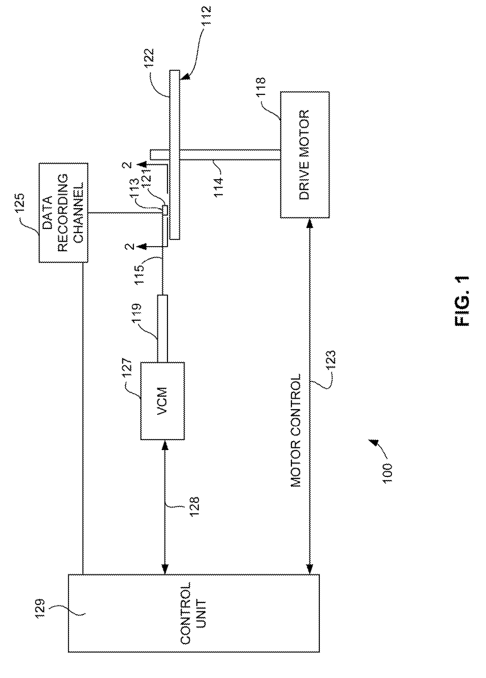
[0044] Referring now to FIG. 1, there is shown a disk drive 100 embodying this invention. As shown in FIG. 1, at least one rotatable magnetic disk 112 is supported on a spindle 114 and rotated by a disk drive motor 118. The magnetic recording on each disk is in the form of annular patterns of concentric data tracks (not shown) on the magnetic disk 112.

[0045] At least one slider 113 is positioned near the magnetic disk 112, each slider 113 supporting one or more magnetic head assemblies 121. As the magnetic disk rotates, slider 113 moves radially in and out over the disk surface 122 so that the magnetic head assembly 121 may access different tracks of the magnetic disk where desired data are written or read....


PUM

PropertyMeasurementUnit
Angleaaaaaaaaaa
Angleaaaaaaaaaa
Depthaaaaaaaaaa

Abstract

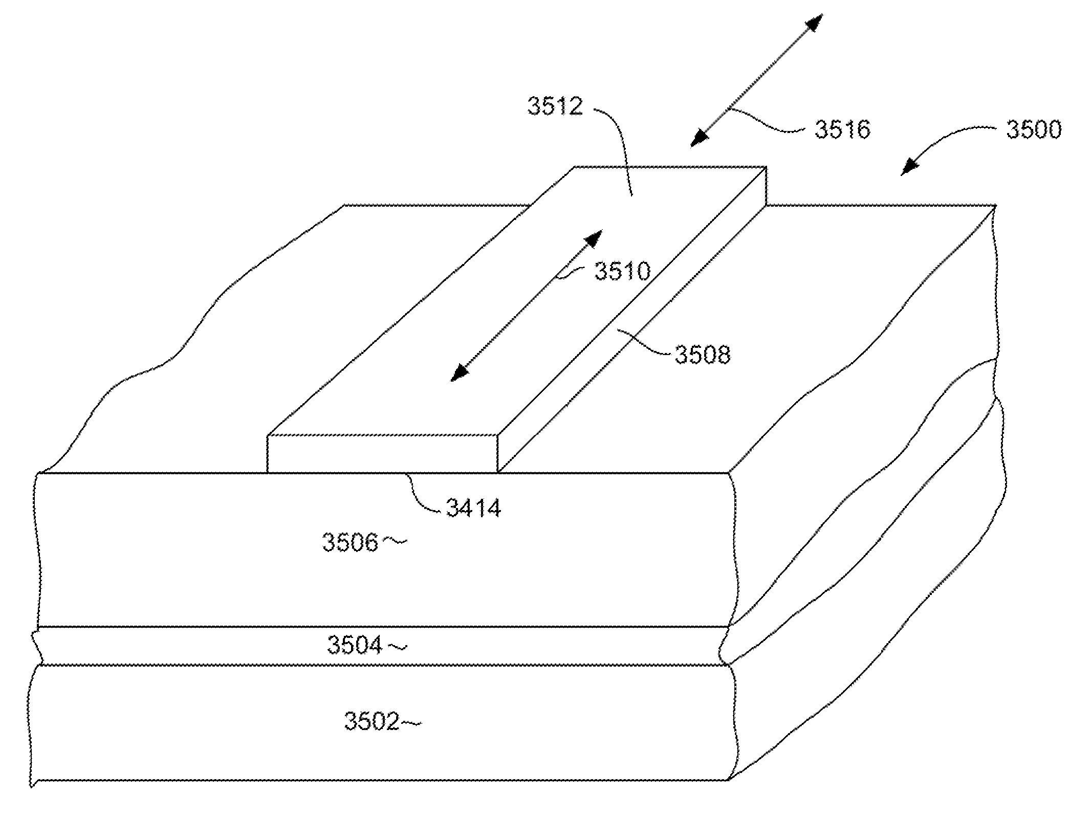
A microwave bandstop filter having a magnetic strip formed over dielectric material. The magnetic resonant frequency is controlled by an induced magnetic anisotropy in the magnetic strip of the microwave bandstop filter. The magnetic anisotropy field is induced by an anisotropic surface texture formed on the surface of the magnetic strip itself, or formed on an underlying layer. Alternatively, the anisotropic surface texture could be formed on both an underlying layer and on the magnetic strip itself. This induced magnetic anisotropy field allows the resonant frequency of the microwave filter to be controlled over a wide frequency range and make high frequency operation possible without reliance on the application of an externally applied magnetic field.

Description

RELATED APPLICATION [0001] This application is a Continuation In Part of commonly assigned U.S. patent application Ser. No. 11 / 542,086 entitled MAGNETIC RANDOM ACCESS MEMORY (MRAM) HAVING INCREASED REFERENCE LAYER ANISOTROPY THROUGH ION BEAN ETCH OF MAGNETIC LAYERS, filed Oct. 2, 2006, which is, itself, a Continuation in Part of commonly assigned U.S. Patent Application entitled MAGNETORESISTIVE SENSOR HAVING MAGNETIC LAYERS WITH TAILORED MAGNETIC ANISOTROPY INDUCED BY DIRECT ION MILLING, application Ser. No. 11 / 304,033 Filed Dec. 14, 2005, both of which are hereby incorporated by reference.FIELD OF THE INVENTION [0002] The present invention relates to magnetoresistive (MR) sensors, and more particularly, to giant magnetoresistive (GMR) sensors having a free layer with a positive magnetostriction wherein the magnetic state of the free layer is stabilized by a strong magnetic anisotropy with an easy axis of magnetization that is produced by anisotropic texturing of the surface of the...

Claims


Application Information

Patent Timeline
IPC IPC(8): H03H7/01H01F7/02
CPCG11B5/3163G11B5/3166G11B5/3196Y10T29/49075G11C11/14H01L43/12G11B5/3932H10N50/01
Inventor CAREY, MATTHEW JOSEPHCHILDRESS, JEFFREY ROBINSONMAAT, STEFAN
Owner WESTERN DIGITAL TECH INC
Why Eureka
Try Eureka