Information-Processing System Using Free-Space Optical Communication and Free-Space Optical Communication System

Inactive Publication Date: 2008-02-21
JAPAN SCI & TECH CORP +1
View PDF5 Cites 220 Cited by
  • Summary
  • Abstract
  • Description
  • Claims
  • Application Information

AI Technical Summary

Benefits of technology

[0024] After the positions of the communication nodes (and any similar light-emitting sources) are detected from the pilot signals, the identification information acquirer obtains identification information of each communication node. In contrast to the above-described process of detecting the pilot signals, in which the detection signals are read from all the micro photo-receiving elements (pixels) of the imaging device, the present process reads detection signals from only a small number of photo-receiving elements within a limited range including the position of each of the communication nodes indicated by the pilot signals. Since the number of pixels to be read is much smaller than in the case of reading all the pixels, the rate of repeatedly reading the same pixel can be set higher. Therefore, it is possible to acquire the identification signal transmitted within a frequency band higher than the frequency of the pilot signal. The identification signal contains identification information, such as an identification number uniquely assigned to every communication node. From this information, it is possible to determine whether the signal source indicated by each pilot signal is actually a communication node or something else. The identification information can also be used to specify a communication node. This information enables users to select a desired communication node, as described later.
[0053] According to this construction, when the user selects one of the communication nodes, the axis of the light emitted from the information terminal to the selected communication node is adjusted. Therefore, at least the information terminal does not need to have a mechanism for mechanically adjusting the optical axis. As a result, the construction is simplified and the production cost of the system is reduced. The operator can intuitively select the communication node by sight. Thus, the system becomes very user-friendly.

Problems solved by technology

However, when, for example, a mobile phone is used for data communication with another device in the above-described conventional infrared data communication, it is not always easy to operate the phone.
However, this adjusting work is not always easy because the user needs to rely solely on his or her senses to check the position of the target device and determine whether the target device is within a range in which the optical communication is performable.
If at least one of the devices concerned is a mobile phone or similar device to be held by hand for operation, the device easily changes its position with the lapse of time due to hand movement, so that it is difficult to continuously maintain the communication in stable condition.
If there is more than one device capable of optical communication within the communication range, the conventional techniques do not allow the user to select one of the devices as the target of the communication.

Method used


Image

  • Information-Processing System Using Free-Space Optical Communication and Free-Space Optical Communication System
  • Information-Processing System Using Free-Space Optical Communication and Free-Space Optical Communication System
  • Information-Processing System Using Free-Space Optical Communication and Free-Space Optical Communication System

Examples


Embodiment Construction

[0069] An embodiment of the free-space optical communication system using an information-processing system according to the present invention is described in detail, with reference to the attached drawings.

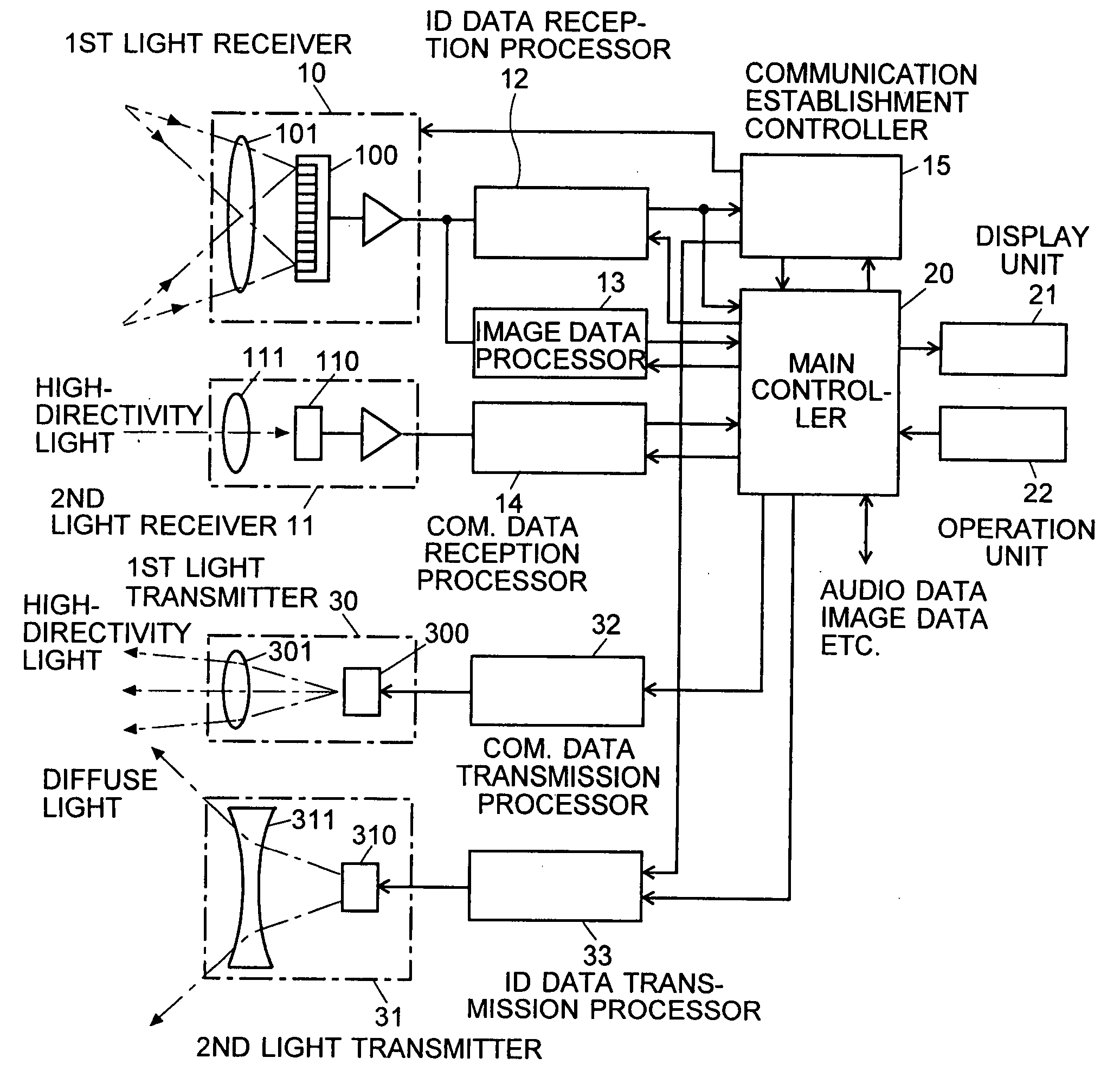
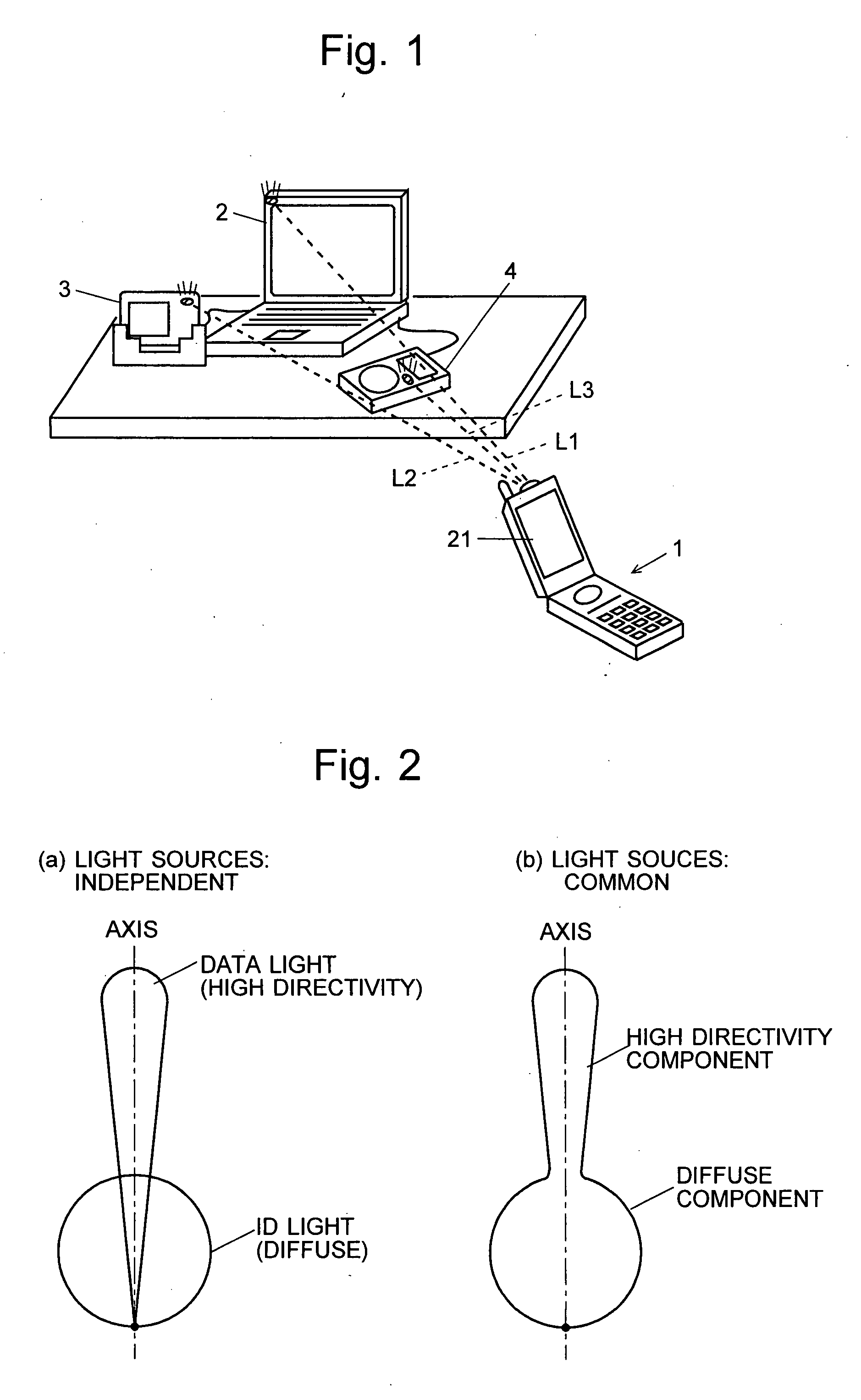
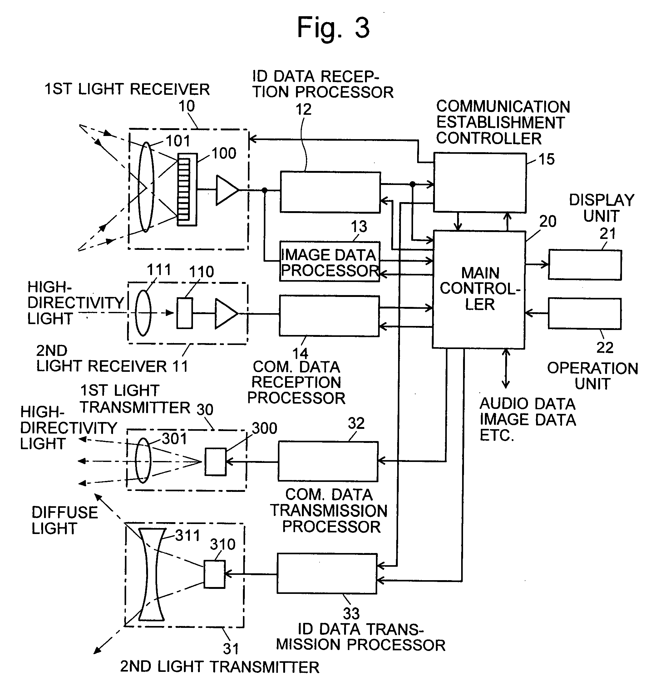
[0070]FIG. 1 is an overall schematic diagram showing a mode of using the free-space optical communication system according to the present embodiment. In this example, the mobile phone 1, which is hand-held by an operator, corresponds to the information terminal of the present invention and is capable of free-space optical communication. The personal computer 2, the digital camera 3 and the portable music player 4, which are located relatively close to each other, are communication nodes capable of two-way communication with the mobile phone 1. The mobile phone 1, the personal computer 2, the digital camera 3 and the portable music player 4 each emit a beam of light containing an ID signal as information (this light called the “ID light” hereinafter). The above-listed devices also...


PUM


Abstract

In a system for data communication between an information terminal to be operated by a user and remote communication nodes, the present invention intends to suppress the power consumption of the information terminal. For that purpose, communication nodes 2, 3 and 4 each emit diffuse light carrying a pilot signal blinking at a low frequency to notify the presence of the communication node and an ID signal belonging to a higher frequency range, the ID signal containing inherent address etc. for identifying each communication node. A mobile phone 1 as the information terminal captures an image and processes the image data to detect the pilot signal of each communication node. Then, determining the position of each node and setting a limited range for reading the pixels around that position, the mobile phone 1 reads the detection signals of the pixels within the limited range at high speed and obtains identification information. This information is used to identify each node and eliminate influences of any other light source that apparently resembles the pilot signal.

Description

TECHNICAL FIELD [0001] The present invention relates to an information-processing system having an information terminal to be operated by a user to collect predetermined items of information from each of two or more communication nodes remote from the information terminal, using free-space optical communication techniques. The present invention also relates to a free-space optical communication system that uses the aforementioned system to establish communications between an information terminal and a communication node using a beam of light or a combination of light and radio waves. BACKGROUND ART [0002] For wireless data communications between personal computers (PCs), mobile information terminals, PC peripheral devices and other devices located relatively close to each other, a standard of infrared data communication called the IrDA (Infrared Data Association) in general is known from, for example, Non-Patent Document 1. The IrDA standard defines a protocol for one-to-one device ...

Claims


Application Information

Patent Timeline
IPC IPC(8): H04B10/10G06K9/46H04W4/00H04B10/07H04B10/11H04W76/02H04W84/10
CPCH04J14/0227H04B10/1141
Inventor KAGAWA, KEIICHIROMAEDA, YUKIOHTA, JUN
Owner JAPAN SCI & TECH CORP
Why Eureka
Try Eureka