Medical handle device and illumination apparatus

a technology of illumination apparatus and medical handle, which is applied in the direction of coupling device connection, light fastening, bore tools, etc., can solve the problems of medical handle device illumination apparatus, noticeably deteriorating light transmission and luminous efficiency, medical handle device illumination, etc., and achieves the effect of easy connection to the surface and better resisting mechanical damag

Inactive Publication Date: 2008-02-21
W&H DENTALWERK
View PDF10 Cites 26 Cited by
  • Summary
  • Abstract
  • Description
  • Claims
  • Application Information

AI Technical Summary

Benefits of technology

[0011] The design according to one exemplary embodiment of the illumination apparatus of the hand-held device having a base body and at least one blind hole arranged in the wall of the base body and a light-emitting window that is formed by the part of the wall extending from the bottom of the blind hole to the first end of the base body has the advantage that a surface facing the treatment site is thereby created, a surface which can better resist mechanical damage. Furthermore, the surface offers a simple option for processing the light emitted by the optical semiconductor element in which the surface of the base bo

Problems solved by technology

However, the illumination apparatus of this medical handle device has many disadvantages.
One disadvantage is that known synthetic resins suitable for this intended application undergo yellowing after repeated sterilization, so the light transmission and luminous efficiency deteriorate noticeably during the lifetime of the medical handle device.
Another disadvantage is that the synthetic resins have a comparatively soft surface.
Since the light is emitted through the synthetic resin, it is located at the surface of the illumination apparatus, and thus there is the risk of mechanical damage to the synthetic resin sheathing.
Furthermore, there is the risk that deep mechanical damage may lead to cracks extending to the LEDs, so that they are no longer protected from water vapor or chemicals, especially during sterilization.
The front surface of the resin facing the t

Method used


Image

  • Medical handle device and illumination apparatus
  • Medical handle device and illumination apparatus
  • Medical handle device and illumination apparatus

Examples


Embodiment Construction

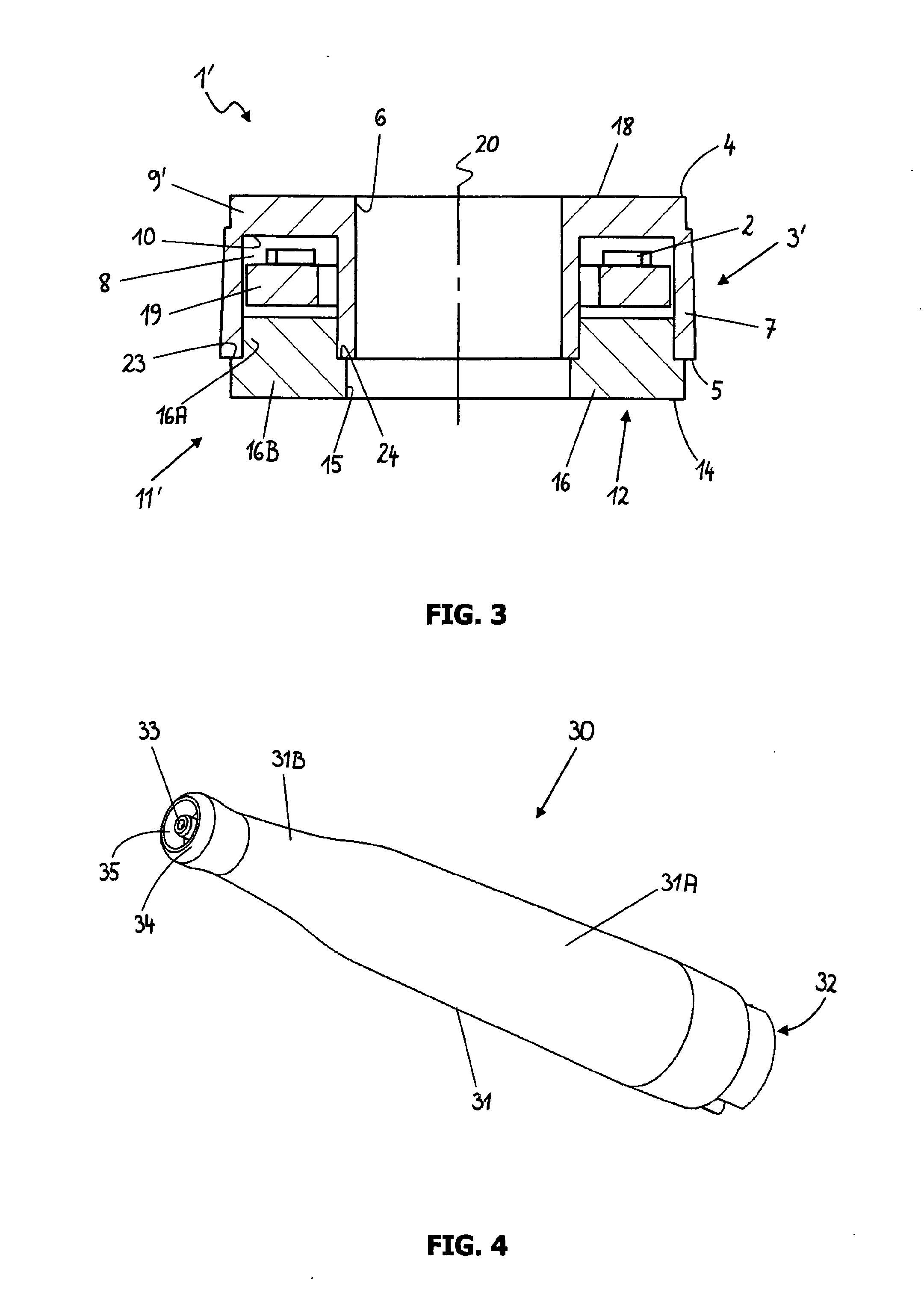
[0071]FIG. 4 shows a dental calculus-removing device, often known as a scaler, as an example of a medical handle device 30. Of course, the term medical handle device is not limited to scalers, but also includes all other hand-held devices that can be used medically, surgically, orthopedically, dentally or cosmetically, in particular medical handle devices that are curved or have sections that are arranged at an angle to one another, medical handle devices having different drives or drive powers, e.g., hand-held devices operated with compressed air, water or electricity, medical handle devices having different tools such as drills, saws, millers, brushes, prophy cups, reamers, shavers, etc., medical handle devices for dispensing laser radiation or medical handle devices whose primary job is to emit light for illumination or for diagnostic, therapeutic or prophylactic treatment. The term hand-held device or medical handle device is also understood to include parts of such hand-held de...


PUM


Abstract

A medical handle device having an illumination apparatus with at least one optical semiconductor component and a method for manufacturing such a hand-held device are displayed. It is proposed that in order to adapt the hand-held device to the specific requirements of a medical application such as uniformly high light emission, high mechanical resistance, sterilizability and electric safety, the illumination apparatus is provided with a base body, at least one blind hole arranged in the base body, a light-emitting window which is formed by the part of the base body extending from the bottom of the blind hole to the first end of the base body and is connected to a cover device which is connected to the base body and with which the blind hole forms a hermetically sealed interior, whereby the at least one optical semiconductor component is arranged in the hermetically sealed interior and the base body and the cover device are made of an electrically non-conducting material that can withstand sterilization. In some embodiments, at least one optical semiconductor component is encased in a transparent thermoplastic material.

Description

CROSS REFERENCE TO RELATED APPLICATIONS [0001] The present application claims priority from pending European Patent Application No. 06012842.8, filed Jun. 22, 2006, and from pending European Patent Application No. 07011078.8, filed Jun. 6, 2007, which are both incorporated herein by reference. BACKGROUND [0002] 1. Field [0003] The present application relates to a hand-held medical handle device having an illumination apparatus with at least one optical semiconductor component as the light source and a method for manufacturing such a medical handle device. [0004] 2. Description of Prior Art [0005] A hand-held medical device or medical handle device having an illumination apparatus with a light-emitting diode (LED) is known from the document EP 1,093,765 A2. The illumination apparatus consists of a holder with a U-shaped cross section in which the LEDs are held and are cast in a transparent heat-resistant synthetic resin. The synthetic resin, originally liquid, is cast into the holder...

Claims


Application Information

Patent Timeline
IPC IPC(8): A61B1/00
CPCA61B1/0607A61B1/24A61C1/088Y10S362/804A61B1/0676A61B1/0684Y10S362/80A61B1/0011
Inventor BRANDSTAETTER, ANDREASSCHALDA, ANTONWENDTNER, WOLFGANG
Owner W&H DENTALWERK
Why Eureka
Try Eureka