Balloon catheter tapered shaft having high strength and flexibility and method of making same

a balloon catheter and tapered shaft technology, applied in the field of medical devices, can solve the problems that the orientation does not significantly increase the bending stiffness of the tubular member, and achieve the effects of low bending stiffness, high rupture pressure, and high tensile strength

Active Publication Date: 2008-02-21
ABBOTT CARDIOVASCULAR
View PDF101 Cites 51 Cited by
  • Summary
  • Abstract
  • Description
  • Claims
  • Application Information

AI Technical Summary

Benefits of technology

[0007]This invention is directed to a catheter having an elongated shaft with a tubular member which forms at least a portion of the shaft and which is formed of a biaxially oriented thermoplastic polymeric material. One aspect of the invention is directed to a method of forming the catheter shaft by radially and longitudinally expanding the tubular member to biaxially orient th

Problems solved by technology

However, the orientation does not significantly in

Method used


Image

  • Balloon catheter tapered shaft having high strength and flexibility and method of making same
  • Balloon catheter tapered shaft having high strength and flexibility and method of making same
  • Balloon catheter tapered shaft having high strength and flexibility and method of making same

Examples


example 1

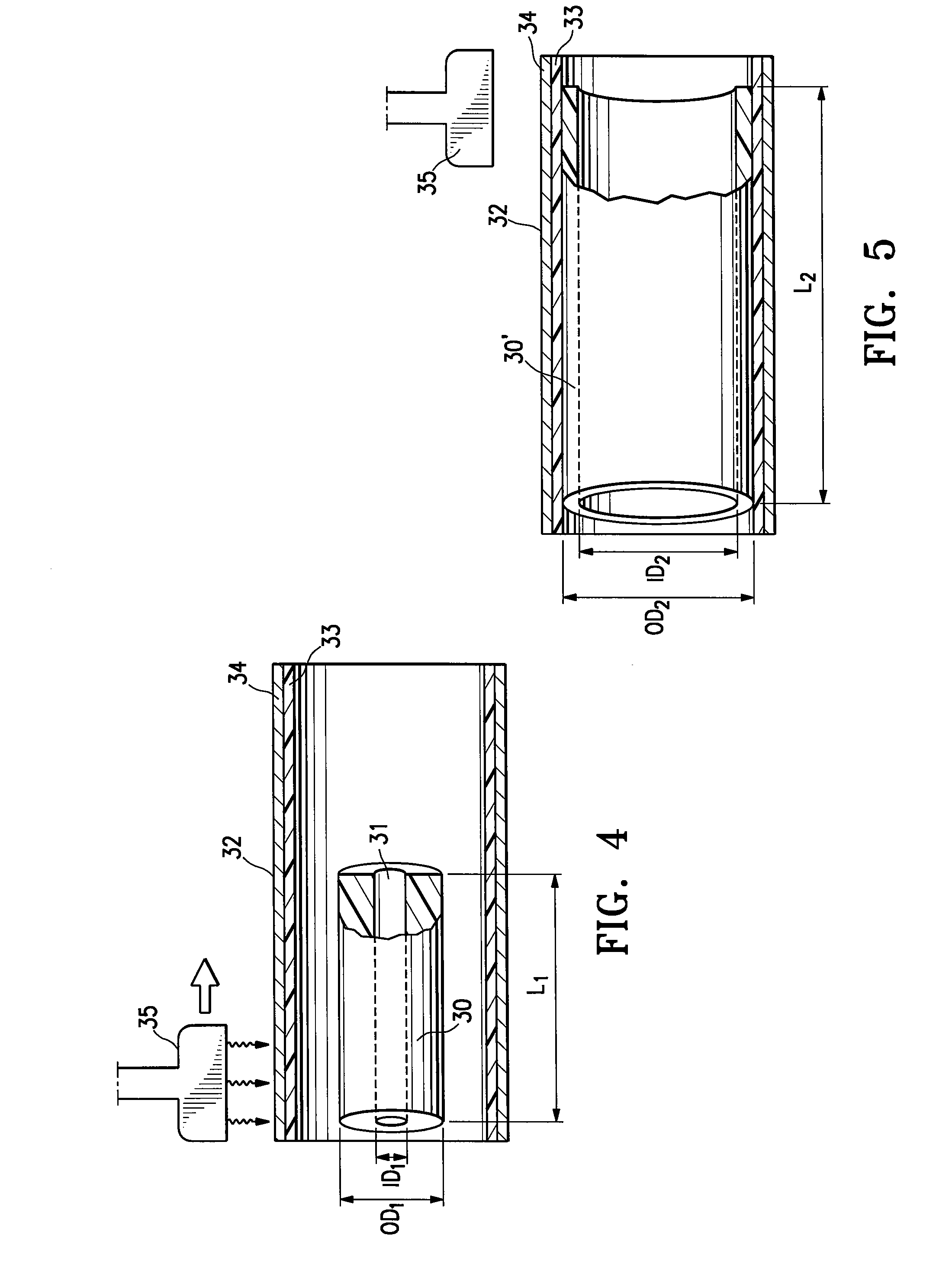
[0079]PEBAX 63D was used to extrude four sets of multiple tubing samples (N=5) having an extruded inner diameter (ID) of about 0.005 inches, and an extruded outer diameter (OD) ranging from about 0.0217 inches to about 0.0264 inches. The extruded tubing was placed inside a stainless steel capture tube having a Teflon liner with an ID of about 0.034 inches, and radially and axially expanded therein at an elevated temperature. Specifically, a vertical hot air necking apparatus was used to pressurize the tubing with pressurized air at about 500 psi and to simultaneously lengthen the tubing with an axial load pulling on one end of the tubing, while the tubing was heated within the capture tube using a heating nozzle traversing along the outside of the capture tube at a set point of about 385° F. (196° C.) (the temperature within the inner chamber of the capture tube is typically less than the set point, and depends upon factors such as the nozzle temperature set point, the nozzle speed,...

example 2

[0081]Equation 3 was used to predict the external weight values required to make a variable outer diameter, constant inner diameter tubular member such as the tapered biaxially oriented tubular member 123 of FIG. 7. The predicted external weight values (using Eq. 3) are tabulated in Table 2 along with the desired as-extruded and final expanded dimensions, the calculated stretch percentages (using Eq. 1), and the calculated total axial stress values (using Eq. 2). In the example set forth in Table 2, the as-expanded outer diameter and wall thickness is to be held constant over the first 20 cm, and then increased linearly over the remaining length. The internal pressure during the biaxial expansion tapering procedure was constant at 475 psi.

TABLE 2AxialAxialStressExternalLocationID1OD1ID2OD2StretchS(total)Weight(cm)(cm)(cm)(cm)(cm)(%)(psi)(grams)0 to 200.0160.0740.0730.0838229.67956560.6220.0160.0740.0730.0848197.86433487.0240.0160.0740.0730.0858171.25272423.9260.0160.0740.0730.086814...

example 3

[0083]To make a variable outer diameter, variable inner diameter, constant wall thickness tubular member such as the tapered biaxially oriented tubular member 135 of FIG. 10, the same conditions as in Example 2 are used, but the external weight decreases by a smaller amount from the 20 cm to the 40 cm axial location. Specifically, to maintain a constant wall thickness of 0.004 inches (0.01 cm) as the outer diameter of the tube increases as in Example 2 from 0.0838 to 0.0939 cm, the axial stretch percentage, total stress, and external weight decrease as set forth in Table 3.

TABLE 3Axial LocationAxial StretchStress (S) (total)External Weight(cm)(%)(psi)(grams)0-20229.67956560.622225.47747547.124221.47547533.726217.47353520.428213.57166507.430209.76986494.432206.06812481.0634202.36644468.936198.86481456.338195.46324443.840192.06172431.4

[0084]The bending moment of inertia (I) can be calculated using the engineering formula for a hollow cylindrical beam, I=(3.14159 / 64)×(OD24−ID24). FIG. ...


PUM

PropertyMeasurementUnit
Lengthaaaaaaaaaa
Fractionaaaaaaaaaa
Fractionaaaaaaaaaa

Abstract

A catheter having an elongated shaft with a tubular member which forms at least a portion of the shaft and which is formed of a biaxially oriented thermoplastic polymeric material, and a method of forming the catheter shaft by radially and longitudinally expanding the tubular member to biaxially orient the polymeric material, and, in one embodiment, tapering the tubular member to form a bending stiffness transition. A catheter of the invention has an improved combination of low bending stiffness, high rupture pressure, and high tensile strength, for improved catheter performance.

Description

CROSS-REFERENCES TO RELATED APPLICATIONS[0001]This application is a continuation-in-part of application Ser. No. 11 / 480,143, filed Jun. 30, 2006, incorporated by reference herein in its entirety.FIELD OF THE INVENTION[0002]This invention relates generally to medical devices, and particularly to intracorporeal devices for therapeutic or diagnostic uses, such as balloon catheters.BACKGROUND OF THE INVENTION[0003]In percutaneous transluminal coronary angioplasty (PTCA) procedures, a guiding catheter is advanced until the distal tip of the guiding catheter is seated in the ostium of a desired coronary artery. A guidewire, positioned within an inner lumen of a dilatation catheter, is first advanced out of the distal end of the guiding catheter into the patient's coronary artery until the distal end of the guidewire crosses a lesion to be dilated. Then the dilatation catheter having an inflatable balloon on the distal portion thereof is advanced into the patient's coronary anatomy, over t...

Claims


Application Information

Patent Timeline
IPC IPC(8): A61M25/10A61F2/958B29C48/09B29C48/10B29C48/11B29C48/13
CPCA61M25/0054A61M25/10A61M25/1036A61M25/104A61M2025/018A61M2025/0183B29C47/0023B29C47/0026B29C47/0028B29C47/0033B29C47/0038B29C47/0057B29C49/00B29C49/04B29C49/08B29C49/18B29C49/64B29C55/26B29C65/02B29C65/48B29C66/534B29C2049/0089B29C2791/001B29D23/001B29K2105/258B29L2031/7542A61M25/1006B29C66/53241A61M25/1029B29L2022/022B29C66/73711B29C66/73713B29C66/1122B29C66/24221A61M25/0021A61M25/0009B29C48/001B29C48/11B29C48/09B29C48/10B29C48/13B29C48/0018B29C2949/08B29C2049/7831B29C49/087B29C2049/7879A61M25/1034A61M2025/1031A61L29/06A61M25/00
Inventor SIMPSON, JOHN A.DURCAN, JONATHAN P.WILSON, BRUCE M.
Owner ABBOTT CARDIOVASCULAR
Why Eureka
Try Eureka