Apparatus and method for bonding anisotropic conductive film using laser beam

a technology of anisotropic conductive film and laser beam, which is applied in the direction of chemistry apparatus and processes, light absorption dielectrics, dielectric characteristics, etc., can solve the problem that the worker does not easily influence the reproducibility of process and quality, and achieves excellent heat transformation effect, easy influence of process and quality, and high optical energy

Inactive Publication Date: 2008-02-28
JET TECH LTD
View PDF3 Cites 9 Cited by
  • Summary
  • Abstract
  • Description
  • Claims
  • Application Information

AI Technical Summary

Benefits of technology

[0011] Therefore, the present invention has been made in view of the above and / or other problems, and it is an object of the present invention to provide an anisotropic conductive film bonding apparatus for heating only a connecting portion using laser beam instead of a hot bar using a heater as a heat source in the thermal-welding for the connection of displays such as LCDs, PDPs, LEDs, or the like using an anisotropic conductive film, such that time for increasing temperature required for the connection is reduced, reliability and reproducibility of the connection process are enhanced by precisely and automatically controlling output of the laser beam, and processing time is also reduced, and a method performed by the anisotropic conductive film bonding apparatus.
[0014] As described above, the anisotropic conductive film bonding apparatus according to the present invention welds the anisotropic conductive film using a laser beam instead of the hot bar as the conventional heat source. The laser beam is absorbed in a portion to be connected and heat is generated therefrom. The heat becomes a heat source for the thermal welding of the anisotropic conductive film. Since the heat is generated from only the connecting portion due to high optical energy per unit area, effect of heat transformation is excellent. Since the output of the laser beam can be precisely controlled, the worker does not easily influence the reproducibility of the process and quality. Moreover, since high energy is provided in a short time and temperature required to connect the anisotropic conductive film can be obtained rapidly, the processing time can be also reduced.

Problems solved by technology

Since the output of the laser beam can be precisely controlled, the worker does not easily influence the reproducibility of the process and quality.

Method used


Image

  • Apparatus and method for bonding anisotropic conductive film using laser beam
  • Apparatus and method for bonding anisotropic conductive film using laser beam
  • Apparatus and method for bonding anisotropic conductive film using laser beam

Examples


Embodiment Construction

[0021] Hereinafter, the preferred embodiment of the anisotropic conductive film bonding apparatus and method according to the present invention will be described in detail with reference to the accompanying drawings.

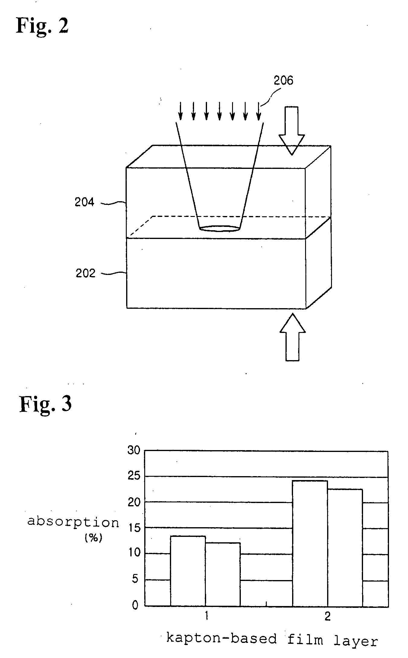
[0022]FIG. 2 is a schematic view illustrating the principle of a laser welding adopted in the present invention, and FIG. 3 is a graph illustrating energy absorption of materials to be connected during the laser welding utilized in the present invention.

[0023] Transmission welding for welding nonmetal or plastic using a laser beam uses the fact that after contacting two materials 202 and 204 to be connected to each other, as shown in FIG. 2, the laser beam is projected to the contacting portion of the media 202 and 204 to generate heat. Referring to FIG. 2, the upper material 204 transmits most of the laser beams being incident in plastic or glass, and the lower material 202, plastic absorbs a predetermined amount of energy of the incident laser beam. The energy of the...


PUM

PropertyMeasurementUnit
temperatureaaaaaaaaaa
thicknessaaaaaaaaaa
wavelengthaaaaaaaaaa

Abstract

An anisotropic conductive film bonding apparatus and a method using a laser beam instead of thermal welding using a hot bar are disclosed. The apparatus includes a light source for generating a laser beam, a laser beam transmitter for guiding the laser beam from the light source to project the laser beam onto a connecting portion, a jig, on which the substrate, the ACF, and the material are accumulated, for projecting the laser beam on the accumulated material, a manipulation panel, and a controller for setting intensity and projection manner of the laser beam and pressure and for controlling overall operation of the apparatus. The process using the hot bar as a heat source for the connection of the anisotropic conductive film is replaced with the process using a diode laser, so that reliability and precision of the process can be achieved, the processing time can be also reduced, and full-automated process can enhance productivity

Description

BACKGROUND OF THE INVENTION [0001] 1. Field of the Invention [0002] The present invention relates to technology for bonding an anisotropic conductive film used to mount electronic components, semiconductors, and flat panel displays such as liquid crystal displays, plasma display panels, electro luminescent displays, and more particularly, to an apparatus and a method for bonding an anisotropic conductive film using laser beam capable of alternating a conventional thermal welding technology due to a hot bar. [0003] 2. Description of the Related Art [0004] Generally, anisotropic conductive films (ACF) are materials, such as double-sided adhesive tapes, formed from minute conductive balls, which are mixed with adhesive and hardened by heat. If high pressure is applied to the ACF, the conductive balls contacting pads (bumps) of a circuit pattern are destroyed such that the conductive balls allow electricity to pass through the pads (bumps), and the adhesives fill uneven surfaces except ...

Claims


Application Information

Patent Timeline
Patent Type & Authority Applications(United States)
IPC IPC(8): B29C65/16
CPCH01L2224/16H01L2924/01079H05K3/323H05K3/3494H05K2203/107H05K2201/0108H05K2201/0112H05K2203/0278H05K3/361H01L2924/00011H01L2924/00014H01L2224/0401
Inventor NAM, GI-JUNGKWAK, NO-HEUNG
Owner JET TECH LTD
Why Eureka
Try Eureka