Device for activating inductive loop sensor of a traffic light control system

a technology of inductive loop and traffic light control, which is applied in the direction of traffic control supervision, mechanical actuation of burglar alarms, instruments, etc., can solve the problems of difficulty in accommodating small vehicles such as bicycles and motorcycles, and the cost of visual systems may not be justified. , to achieve the effect of convenient adjustmen

a technology of inductive loop and traffic light control, which is applied in the direction of traffic control supervision, mechanical actuation of burglar alarms, instruments, etc., can solve the problems of difficulty in accommodating small vehicles such as bicycles and motorcycles, and the cost of visual systems may not be justified. , to achieve the effect of convenient adjustmen

US20080048888A1Inactive Publication Date: 2008-02-28RICHLEY EDWARD ANTHONY

Image

  • Device for activating inductive loop sensor of a traffic light control system
  • Device for activating inductive loop sensor of a traffic light control system
  • Device for activating inductive loop sensor of a traffic light control system

Examples


Embodiment Construction

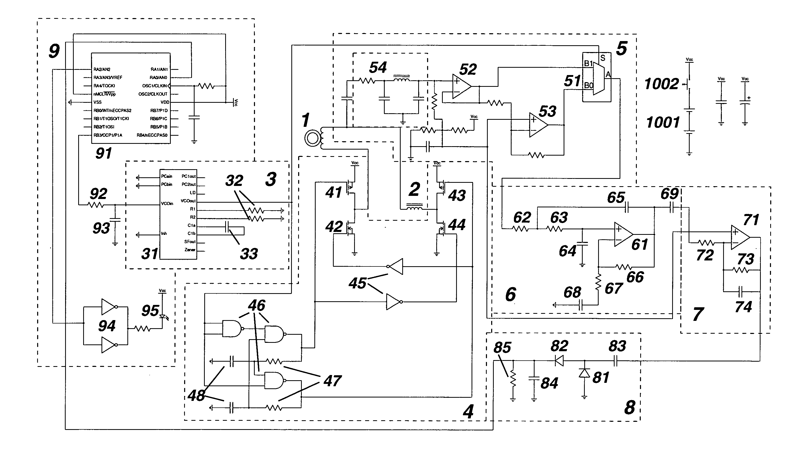
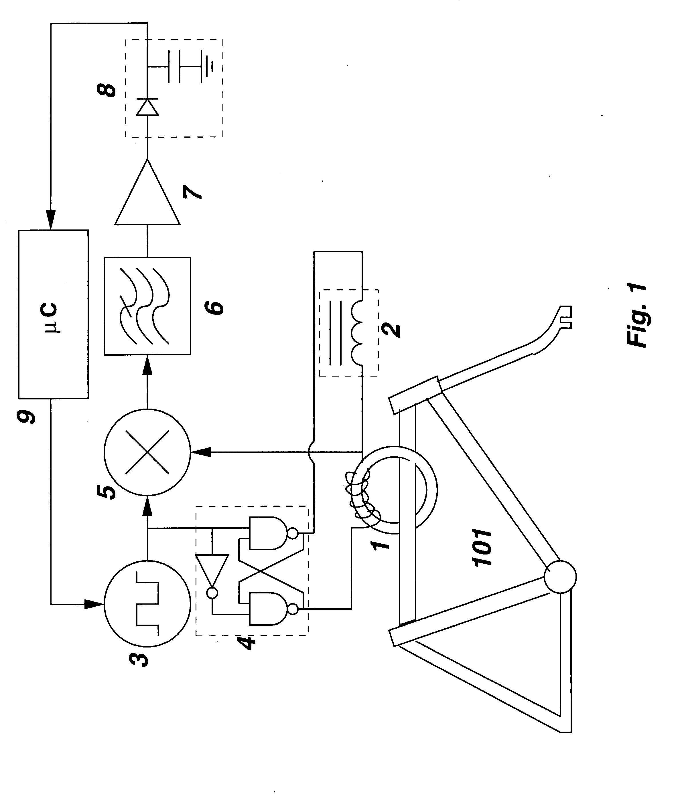
[0027]FIG. 1 shows a block diagram of an exemplary embodiment of the invention. Transformer 1 serves to both carry the high-power output signal being sent to the bicycle frame, as well as to transfer the much weaker signal emitted by the sensor loop back to the activation electronics. Balanced drive circuitry 4 takes the signal from VCO 3, which is constrained to have a frequency covering all the expected operating frequencies of loop sensors (typically 20 kHz-200 kHz) and applies it to both the primary winding of transformer 1 and inductor 2. Transformer 1 consists of approximately 8 turns of copper foil wound on a split toroidal ferrite, approximately 2 inches in overall diameter. It has been found that a practical value for the inductance as measured at the primary winding of transformer 1 is 50 microhenries. Thus, the magnetization inductance of transformer 1 should be substantially larger than this value, so that maximal current is transferred into vehicle frame 101. Inductor 2...


PUM


Abstract

A system and method for activating vehicle sensors which are based on inductive loops. A transformer is used to couple the vehicle frame to activation circuitry. Within the activation circuitry, a voltage controlled oscillator which drives the transformer is scanned throughout the required frequency range while a balanced mixer, low-pass filter, and detector are arranged to show the presence of a signal from an inductive loop by the amplitude of the resultant signal at a difference frequency. The voltage controlled oscillator is then made to dwell at or near the frequency of the sensor loop by adjusting so as to keep the amplitude of that low-frequency difference as high as possible.

Description

RELATED APPLICATIONS[0001]This application claims priority under 35 USC section 120 from copending U.S. application Ser. No. 11 / 511,115 filed on Aug. 28, 2006, the specification of which is expressly incorporated herein by reference.FIELD OF THE INVENTION[0002]This invention relates to the field of automated traffic control systems, particularly those with vehicle presence sensors based on inductive loops buried beneath a roadway. More specifically, this invention relates to the field of devices for enhancing the ability of smaller vehicles to activate such sensors.DESCRIPTION OF RELATED ART[0003]Control of traffic signal lights by automatic vehicular sensors has become very common throughout the world, as an alternative to signal control based purely on timing.[0004]Although many modern vehicle sensing systems are based on digital cameras with pattern recognition software, many older and less costly systems are based on detection of a change in inductance of a loop of wire buried b...

Claims


Application Information

Patent Timeline
28 Feb 2008
Publication
US20080048888A1
IPC
G08G1/01
CPC
G08G1/042; G01D5/204
Inventors
RICHLEY, EDWARD ANTHONY