Helmet System for Information or Weapon Systems

a technology of information or weapon system and helmet, which is applied in the field of helmets, can solve the problems of high labor intensity and set-up procedure of magnetic insufficient inertial sensor of helmet, optical helmet position sensing system,

Inactive Publication Date: 2008-02-28
THE STATE OF ISRAEL MINIST OF AGRI & RURAL DEV AGRI RES ORG ARO VOLCANI CENT
View PDF11 Cites 70 Cited by
  • Summary
  • Abstract
  • Description
  • Claims
  • Application Information

AI Technical Summary

Benefits of technology

[0042]There is also provided according to the teachings of the present invention, a method for reliable real-time calculation of pupil gaze direction over a wide range of angles, the method comprising: (a) illuminating an eye with electromagnetic radiation of at least one wavelength, (b) obtaining an image of the illuminated eye; (c) identifying within the image a pupil location; (d) automatically determining whether the image includes a direct corneal reflection; (e) if the image does not include a direct corneal reflection, calculating a current pupil gaze direction based upon the pupil location, the calculating being performed using a pupil-only gaze direction model, (f) if the image does include a direct corneal reflection, deriving a current pupil gaze direction based upon both the pupil location and a position of the direct corneal reflection.

Problems solved by technology

For moving platforms, however, helmet-mounted inertial sensors are not sufficient due to the non-inertial (i.e., subject to acceleration) nature of the platform itself.
Most notably, the use of magnetic helmet position sensing systems has a highly labor intensive set-up procedure, requiring time-consuming mapping of the magnetic fields of the entire cockpit environment, and requiring re-mapping whenever a change is made to the cockpit arrangement.
Optical helmet position sensing systems, on the other hand, suffer from their own disadvantages.
In either case, the process of integration requires re-evaluation and testing for the safety, operational and reliability standards required by the relevant aviation authorities, a process which is typically very costly and may take months or years.
As a result, the implementation of each subsystem inherently requires some significant degree of integration into the cockpit environment.
However, the pupil-plus-glint mode is only operative over a relatively small range of angles where the direct corneal reflection is visible to the imaging sensor.
As a result, no currently available system is capable of tracking eye-movements over a wide range of angles while also compensating for errors due to shifting of aliment and other mechanical disturbances.

Method used


Image

  • Helmet System for Information or Weapon Systems
  • Helmet System for Information or Weapon Systems
  • Helmet System for Information or Weapon Systems

Examples


Embodiment Construction

[0056]The present invention provides a helmet position measuring system and a helmet mounted eye-gaze direction sensing system, together with associated methods.

[0057]The principles and operation of systems and methods according to the present invention may be better understood with reference to the drawings and the accompanying description.

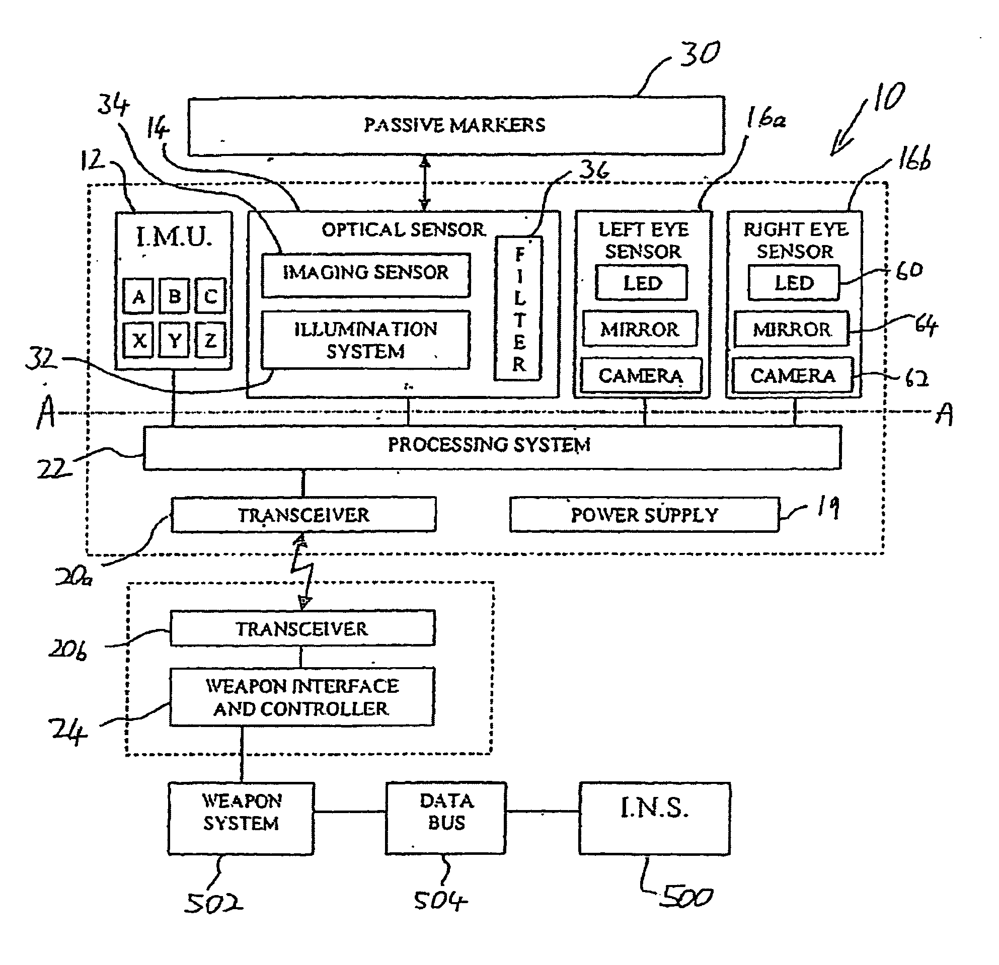
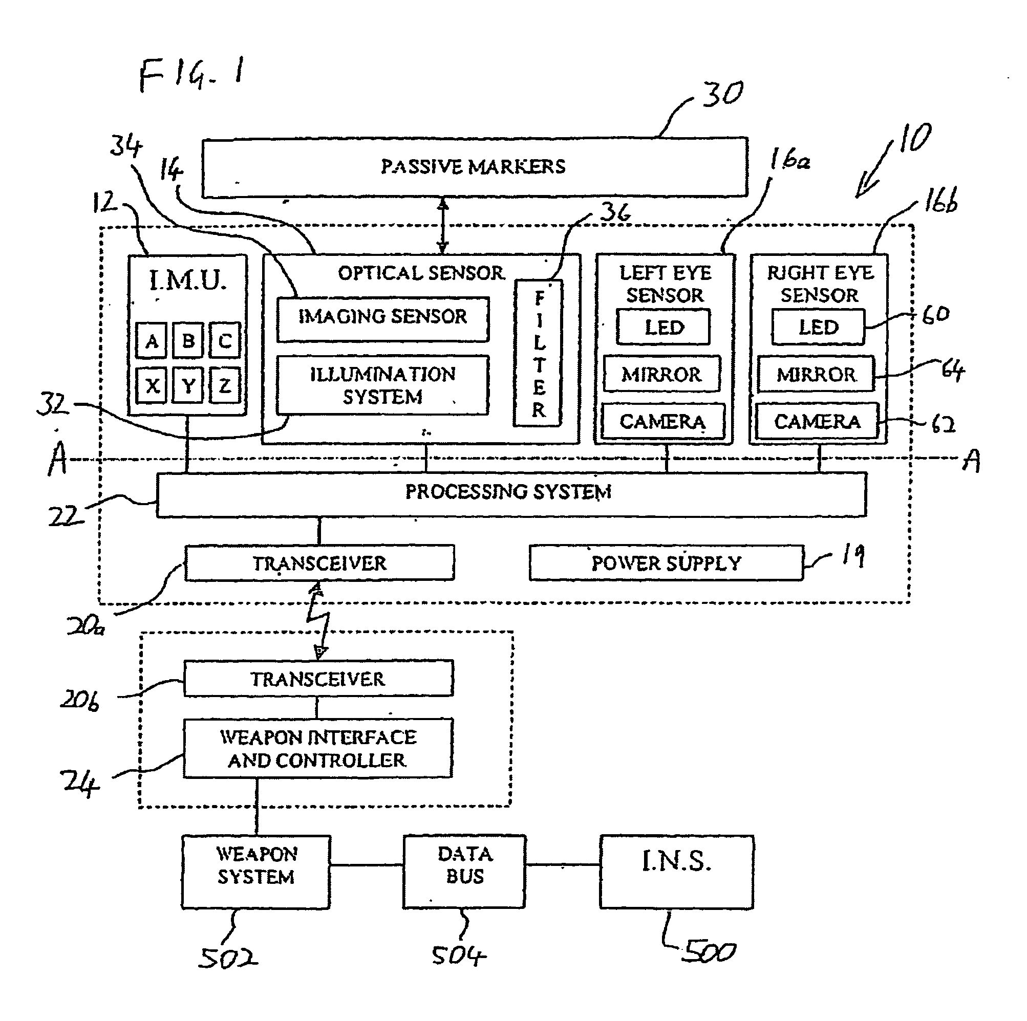
[0058]Referring now to the drawings, FIG. 1 shows a helmet system, generally designated 10, constructed and operative according to the teachings of the present invention, together with a number of related components. In general terms, the preferred embodiment of helmet system 10 shown here includes a number of subsystems each of which has utility in itself when used together with various otherwise conventional systems, but which are synergiously combined in the preferred embodiment as will be described. These subsystems include a helmet tracking system based upon one, or preferably both, of an inertial sensor system or inertial measurement unit (...


PUM


Abstract

A helmet position measuring system for use in a predefined environment. The system includes a helmet-mounted illumination system for directing electromagnetic radiation of one or more wavelength from the helmet in one or more range of angles, a set of three or more passive reflectors deployed at fixed positions in the predefined environment to reflect electromagnetic radiation from the illumination system, a helmet-mounted imaging system sensitive to the one or more wavelength for deriving images of part of the predefined environment including electromagnetic radiation reflected from the reflectors, and a processing system associated with the imaging system for processing the images to identify regions of the images corresponding to the reflectors and hence to determine information relating to a position of the helmet within the predefined environment.

Description

FIELD AND BACKGROUND OF INVENTION[0001]The present invention relates to helmets for use in automated systems and, in particular, it concerns a helmet system for use with weapon or information systems which requires minimal integration with other systems. Various aspects of the invention relate to a helmet position tracking system and an eye-motion tracing system, and the associated methods of operation.[0002]It has become increasingly common for automated systems, particularly in the field of aeronautics, to employ systems integrated with a helmet worn by a pilot as an inter part of an automated system. For example, in helmet sights, a helmet position sensing system follows the angular position of the helmet and directs a weapon system to align with a fixed sight mounted on the helmet. In more sophisticated systems, a helmet mounted display (HMD) provides numerous additional features, including providing visible indicators aligned with objects viewed by the pilot.[0003]In all such s...

Claims


Application Information

Patent Timeline
Patent Type & Authority Applications(United States)
IPC IPC(8): G09G5/00G02B5/12G02B27/14G06F
CPCA42B3/0433A61B3/113A61B5/11A61B5/6814A61B2562/0219F41G3/225G06F3/0346G01S5/163G02B27/017G02B2027/0187G06F3/012G06F3/013G06F3/0304G01C21/165G01C21/1656G06F3/00G06F1/00
Inventor BEN-ARI, TSAFRIR
Owner THE STATE OF ISRAEL MINIST OF AGRI & RURAL DEV AGRI RES ORG ARO VOLCANI CENT
Why Eureka
Try Eureka