

Light emitting device including anti-reflection layer(s)
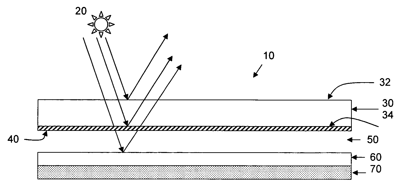
a technology of light emitting device and anti-reflection layer, which is applied in the direction of refractors, coatings, lighting and heating apparatus, etc. it can solve the problems of ambient lighting creating visible interference fringes via constructive/destructive, affecting the appearance of newton's rings, and not typically providing hermetic seals in sealant systems, etc. , to achieve the effect of reducing the internal reflection of ambient light, reducing the presence of newton's rings
- Summary
- Abstract
- Description
- Claims
- Application Information
AI Technical Summary
Benefits of technology
Problems solved by technology
Method used
Image

Examples
example 1
Single Layer MgF2 Coating
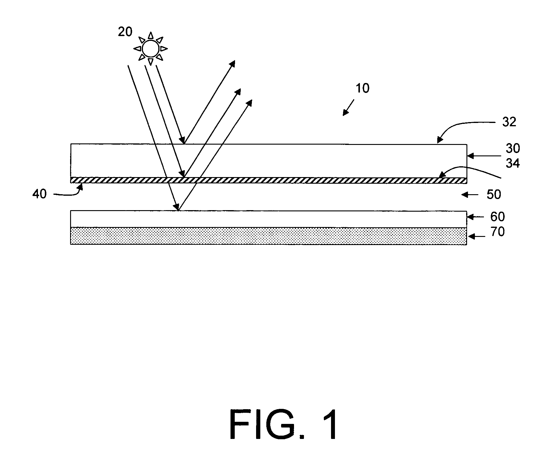
[0062]In a first example, a single layer magnesium fluoride coating was modeled on one surface of a piece of Eagle2000™ glass, simulating the inner surface of a light emitting device cover substrate. The refractive index of the Eagle2000™ glass of this example is 1.507 at 589.3 nanometers, and thus, according to the theory set forth above, the anti-reflective coating has a target refractive index of 1.23 and an optical thickness of 147 nanometers. A single layer magnesium fluoride coating has a refractive index of 1.38, and thus a physical thickness of about 107 nanometers.
[0063]FIG. 2 illustrates the modeled reflectivity of light at various angles of incidence for the single layer magnesium fluoride coating. At a wavelength of 546 nanometers, the reflectance is approximately 1.4% when viewed from an angle of incidence of from 0 to 30 degrees. At a 45 degree angle of incidence, the reflectance is slightly greater than 2 percent, and at a 60 degree of inciden...
example 2
Multi-Layer Coatings
[0064]In a second set of examples, a series of models were conducted to determine reflectivity of ambient light for a cover substrate coated with a multi-layer anti-reflective coating. A three layer and a twelve layer anti-reflective coating were modeled at various angles of incidence. The three layer coating model represents a typical anti-reflective coating design on an Eagle2000™ glass substrate. The index of refraction and physical thickness of each of the 3 layers were: 1.62 and 83 nanometers; 2.32 and 116 nanometers; and 1.38 and 98 nanometers, respectively. The twelve layer coating was more complex, requiring substantially thinner layers, and as such, optimization was performed by computer to accommodate the large number of variables.
[0065]FIG. 3 illustrates the modeled reflectivity of light at an angle of incidence of 0 degrees for both a 3 layer and a 12 layer anti-reflective coating. For both coatings, reflectance was significantly below 1 percent at 54...
example 3
Four Layer Anti-Reflective Coating
[0069]In still a third example, a four layer anti-reflective coating was modeled on an Eagle2000™ cover substrate. The four layer coating comprised 12 nanometers niobium oxide, about 36 nanometers silica, about 110 nanometers niobium oxide, and a top layer of 90 nanometers silica.
[0070]As illustrated in FIG. 7, the modeled reflectance of light at angles of incidence up to 45 degrees is less than 1 percent for visible wavelengths below 630 nanometers. This model suggests that this coating composition is sufficient to reduce observation of Newton's Rings at angles of incidence up to about 45 degrees.
PUM
| Property | Measurement | Unit |
|---|---|---|
| Angle | aaaaa | aaaaa |
| Angle | aaaaa | aaaaa |
| Nanoscale particle size | aaaaa | aaaaa |
Abstract
Description
Claims
Application Information