
Plasma Generation Device

a generation device and plasma technology, applied in the field of plasma generation devices, can solve the problems of high voltage requirements, high power consumption, and waste of working gas decomposition energy, and achieve the effect of less power consumption, efficient plasma generation, and no extra energy wasted

Inactive Publication Date: 2008-02-28
YUTAKA ELECTRONICS IND
View PDF0 Cites 34 Cited by
  • Summary
  • Abstract
  • Description
  • Claims
  • Application Information

AI Technical Summary

Benefits of technology

The present invention provides a plasma generation device that can efficiently generate plasma at atmospheric pressure without generating an arc discharge. The device uses a pulse power supply to provide a pulse voltage to a coaxial cylindrical electrodes system, which induces an electric discharge to generate plasma. Compared to prior-art devices that use arc discharge, the present invention has several advantages, including lower power consumption, no high calorie or fast dissolution of electrodes, and less extra energy wasted for decomposing the working gas. The device can also form a discharge path even at a low discharge voltage and requires less heat generation.

Problems solved by technology

Using the arc discharge for decomposing the working gas as in the prior art, however, involves several problems, including high voltage requirements, high power consumption, extra energy wasted for decomposing the working gas by heat, a high calorie generated for generating plasma, and fast dissolution of electrodes.

Method used


Image

  • Plasma Generation Device
  • Plasma Generation Device
  • Plasma Generation Device

Examples


Embodiment Construction

[0029]The present invention will now be described in detail with reference to the accompanying drawings.

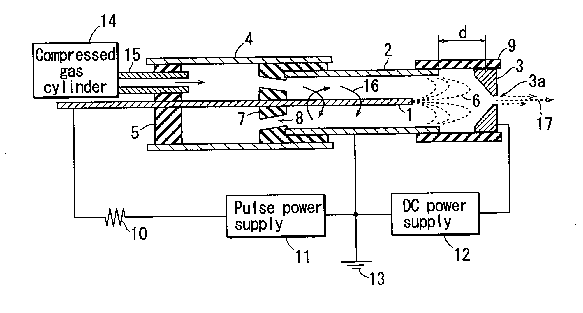
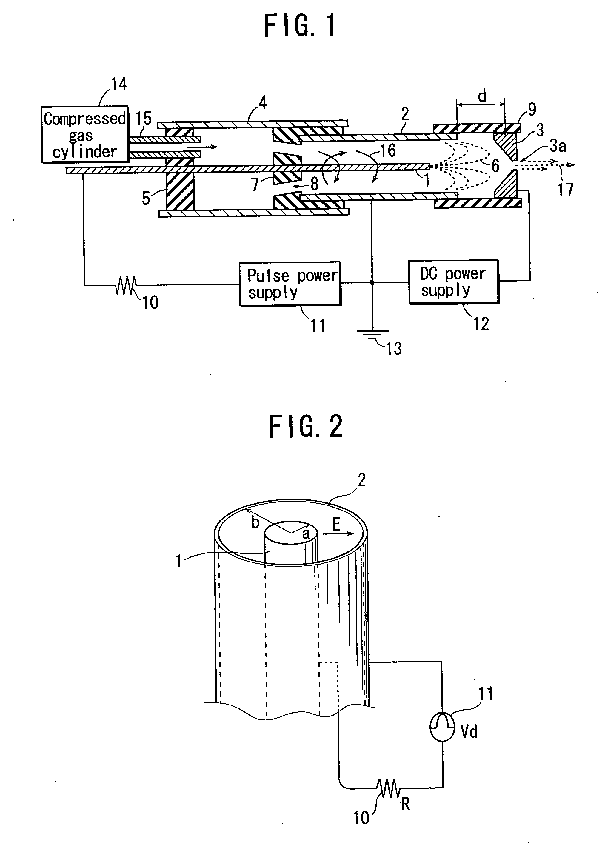
[0030]FIG. 1 is a sectional block diagram schematically showing the structure of a plasma generation device according to an embodiment of the present invention.

[0031]An example of an electrode bar 1 is a bar of 0.6 mm in diameter made of iridium alloy, tungsten, or stainless steel. An example of cylindrical electrode 2 is a cylindrical stainless steel pipe of 4.3 mm in internal diameter.

[0032]An example of a casing 4 is a cylindrical tube of 10 mm in internal diameter made of acryl or other resin, or stainless steel (SUS) or other metal if the casing 4 is insulated from the electrode.

[0033]A bottom member 5 is a disk member that fits inside the casing 4 and has holes therethrough for receiving the electrode bar 1 and a gas injection pipe 15. The bottom member 5 is made of an insulating material.

[0034]A support member 7 also fits inside the casing 4, as does the bottom member 5, an...


PUM


Abstract

A plasma generation device that can efficiently generate plasma at atmospheric pressure without producing arc discharge is provided. The plasma generation device, which comprises an electrode bar 1, a cylindrical electrode 2, and a pulse power supply 11 generating a pulse voltage, generates plasma by an electric discharge induced between the electrode bar 1 and cylindrical electrode 2 by applying a predetermined pulse voltage to a point between the electrode bar 1 and cylindrical electrode 2.

Description

[0001]This is a U.S. national stage of PCT Application No. PCT / JP2005 / 018457 filed on Oct. 5, 2005, claiming priority from Japanese Patent Application No. 2004-303240 filed on Oct. 18, 2004.FIELD OF THE INVENTION[0002]The present invention relates to a plasma generation device that generates plasma at atmospheric pressure rather than in a sealed vacuum or other pressure-controlled environment.BACKGROUND OF THE INVENTION[0003]Recently, there are increasing needs to generate plasma at atmospheric pressure. The plasma may be used to modify the surface of an object, for example.[0004]As one known example of an application of such surface modification, plasma can be used to roughen a polypropylene (hereinafter “PP”) surface before printing thereon, as the polypropylene surface is otherwise too smooth to hold ink.[0005]Roughening the surface of an object also increases its adhesiveness when an adhesive is applied for bonding.[0006]Use of an electric discharge to generate plasma is well kn...

Claims


Application Information

Patent Timeline
Patent Type & Authority Applications(United States)
IPC IPC(8): B01J19/12
CPCH05H1/24H05H1/52H05H1/47H05H1/473
Inventor NAGASAWA
Owner YUTAKA ELECTRONICS IND
Learn More